I'm having trouble finding an equivalent for a 2SC9012 and 2SC9013. The closest I can get is a BC327 and BC337 respectively.
I'm just a beginner, and I'm not confident I'm reading the data sheets correctly. Would the BC327/337 be a suitable replacement for a 9012/9013 respectively?
Thanks in advance.
I'm just a beginner, and I'm not confident I'm reading the data sheets correctly. Would the BC327/337 be a suitable replacement for a 9012/9013 respectively?
Thanks in advance.
I think that part number is wrong or a wild guess often repeated by parts sellers and users. I don't believe there is such a transistor as 2SC9012 (sic) etc. The original part numbers are most likely S9012,3 and are in a series of similar "S" numbered low cost parts made originally by Fairchild/National Semiconductor in Malaysia for use in plastic case boom boxes and similar everyday consumer gear of the eighties. You'll now find them cheap and plentiful on Ebay but you don't often find them in distributors catalogues because there are so many unlicensed manufacturers of these frequently copied components.
You can Google datasheets from quite a number of suppliers and this example applies to a more reliable US source but I can't say it applies to any others you may find on Ebay. For example:
https://www.digchip.com/datasheets/parts/datasheet/284/S9012-pdf.php
https://www.onsemi.com/pub/Collateral/BC327-D.PDF
Simple checks of suitability are to look at:
Vceo - the allowable max. voltage between collector and emitter - Is it enough for your circuit? The BC327 is rated at 45V and should be fine since 9012 is only 25V.
Iceo - the maximum rated current - is listed 0.5A but BC327 is 0.8A so again, plenty of capability.
hfe - this is the DC gain of the transistor and the figures can be quite broad for both types. Generally though, the gain is less for 9012. In either case, you should always test whether hfe is within a suitable range and according to any particular grade marking (-25, -40 variations if applicable) with a suitably featured multimeter or other transistor tester, before fitting. Generally, if you'e going to substitute semis, test the basics first, so you know the likely places to look when things don't work properly.
Really though, the actual circuit application determines what will be a suitable substitute. Without knowing the application, substitutions could range from using only the specified type to any PNP transistor will do. I suspect that basic BC327/337 types will be fine but why not post your application for a quick check, if that's your real concern?
Last edited:
I think that part number is wrong or a wild guess often repeated by parts sellers and users. I don't believe there is such a transistor as 2SC9012 (sic) etc. The original part numbers are most likely S9012,3 and are in a series of similar "S" numbered low cost parts made originally by Fairchild/National Semiconductor in Malaysia for use in plastic case boom boxes and similar everyday consumer gear of the eighties.
I think you're right Ian. There are loads of S90xx parts on EBay. I assumed it was 2SC9012 etc because there as such a device, and I can find datasheets on it... and it's also a TP92 package, but when you mentioned S90xx and 80s TVs it does actually make sense. The circuit I was going to make was a low power amplifier I need for an active speaker I am making. I already ordered some BC3xx parts from Farnell though, as they were cheap
You'll now find them cheap and plentiful on Ebay but you don't often find them in distributors catalogues because there are so many unlicensed manufacturers of these frequently copied components.
You can Google datasheets from quite a number of suppliers and this example applies to a more reliable US source but I can't say it applies to any others you may find on Ebay. For example:
https://www.digchip.com/datasheets/parts/datasheet/284/S9012-pdf.php
https://www.onsemi.com/pub/Collateral/BC327-D.PDF
That would be my worry with Ebay - cheap copies.
Really though, the actual circuit application determines what will be a suitable substitute. Without knowing the application, substitutions could range from using only the specified type to any PNP transistor will do. I suspect that basic BC327/337 types will be fine but why not post your application for a quick check, if that's your real concern?
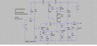
It's a low power amp I found on somewhere on the internet. Not much information about it, but it mentions being widely used in 80s for a range of tv audio amplifiers. It looked simple, and probably perfect for my needs.
I wanted to build a discreet amp, simple because I like building things. So many circuits found on the internet seem to not work though. As a beginner, I find it hard to spot problems with circuits as a schematic though. I'm trying to get to grips with LTSpice, but I'm not quite there with that yet.
I've included the schematic in this post.
Thank you.

Save
The schematic says 9012 and 9013... I just assumed 2SCxxxx
The BU406 as an output looks odd. BU devices are typically high voltage and low gain and have their origins in TV line output stages. Something like a TIP41 would make much more sense.
The drivers are non critical and given the low supply pretty much anything would work. BD131 and BD132 come to mind as good general purpose devices for experimenting with.
The drivers are non critical and given the low supply pretty much anything would work. BD131 and BD132 come to mind as good general purpose devices for experimenting with.
The BU406 as an output looks odd. BU devices are typically high voltage and low gain and have their origins in TV line output stages. Something like a TIP41 would make much more sense.
The drivers are non critical and given the low supply pretty much anything would work. BD131 and BD132 come to mind as good general purpose devices for experimenting with.
I chose this because I had some BU406s lying around.. no idea where they came from now.
As I'm still learning here, I just wanted to build something that would work in the meantime, but maybe I'm being a bit too optimistic in that department
")
I really need to build this active speaker though, so maybe I'd be better served searching these forums for a a tried and tested design I can just build, knowing it will work in the meantime.
I've built a few designs I've found on the net, and they never seem to work for me. I'm not sure now... is it me... or are the designs flawed. I'm sure when I know more I'll be able to work it out for myself, but I just don't have the knowledge right now to look at a schematic and identify problems.
Thanks for the help so far.
It looks a very workable and forgiving circuit. The only thing I would beware of is the fixed bias arrangement... perhaps initially power it up with one of the three diodes shorted to further reduce current.
Have you actually simulated this one ?
I can tell you from the circuit topology that this one will sound really good.
Have you actually simulated this one ?
I can tell you from the circuit topology that this one will sound really good.
Actually, and just studying the circuit in more detail I can see one possible error. R9 is way to small at 10 ohms. The gain of the circuit is set by the ratio of R4 to R9 and 10 ohms is way to small. Something like a 150 or 180 ohm would be suitable. C4 could do with being a little larger as it sets a low frequency roll off point for the feedback network. 220uF or 470uF should be OK there.
The basic circuit will work though... its a classic arrangement.
The basic circuit will work though... its a classic arrangement.
It looks a very workable and forgiving circuit. The only thing I would beware of is the fixed bias arrangement... perhaps initially power it up with one of the three diodes shorted to further reduce current.
Have you actually simulated this one ?
I can tell you from the circuit topology that this one will sound really good.
I've not simulated it, no.... I was just going to build it on breadboard, which is why I was asking about the 90xx replacement.
I'll build it and see what happens....
...what's the worst that can happen
The BU406/7 has an average hfe of only 7!
The 2SC9012 is now known as a KTC9012 as is the 9013 and are readily available.
As Mooly stated, I would also go for the Tip range of output transistors as the BU406 will not amplify the current required to let the 2SC9012/3 work properly.
I have serviced Television and Video since 1972 and have never come across the BU type transistor being used in audio applications due to the switching parameters.
...btw... your LTSpice links are great! Thanks.
Thanks
(I might simulate this amp and then we can see where its at performance wise)
That may be useful!
Simulate it with BC327 for 9012 and 337 for 9013.. and BU406 finals, as that's what I have here. As JonSnell said though... does seem an odd choice. Where I got the schematic from though, shows a built up version and the guy reckons it works well and sounds good (with 406s).
I'm intrigued now.
Simulate it with BC327 for 9012 and 337 for 9013.. and BU406 finals, as that's what I have here. As JonSnell said though... does seem an odd choice. Where I got the schematic from though, shows a built up version and the guy reckons it works well and sounds good (with 406s).
I'm intrigued now.
I would doubt there are any models kicking around for the BU's tbh.
They would undoubtedly work but they are an odd (poor imo) choice given that they are optimised for high voltage high current switching. They needs lots of driving (high base current due to low forward gain) and that would pull the performance of the amp down.
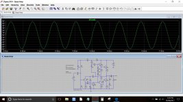
I'll throw a simulation of it together.
They would undoubtedly work but they are an odd (poor imo) choice given that they are optimised for high voltage high current switching. They needs lots of driving (high base current due to low forward gain) and that would pull the performance of the amp down.
I'll throw a simulation of it together.
Here you go. The asc file and TIP41C model is attached so you can have a play in LT.
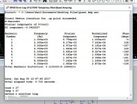
Edit... if you have a play with this then take a look at the standing DC current in the output stage with the TIP41C models. Now try changing those to the standard 2N3055 and recheck. You can also try altering the 220 ohm (R9) and seeing the effect on the gain. R2 at 75k in my diagram is really the combined value of the 15k plus the pot value needed to get symmetrical clipping.
I've also added the BD131/132 and S9012 and 9013 models to the list. Be sure to enter them as written in the text document, for example the 9013 is ss9013
Model for the BU406. Copy and paste into the text document:
Code:
.MODEL BU406 NPN (IS=9.9822F BF=55.108 NF=1.02229 VAF=100 IKF=4.2725 ISE=40.1051P NE=1.96698 BR=138.579M IKR=999.958M ISC=14.8407P RE=61.0112M RC=99.1446M CJE=2P MJE=500M CJC=366.438P VJC=700M MJC=558.067M TF=14.9903N XTF=500M VTF=10 ITF=16.299M TR=10N Vceo=375 Icrating=6 mfg=Texas)Attachments
Thanks for doing that. I really appreciate it.
I got home this afternoon to find my cable modem dead, and virgin cant get out here until tuesday so i cant do anything until then. Just got my phone until then but ill play more then and order some TIP41s in the meantime.
Thanks again.
I got home this afternoon to find my cable modem dead, and virgin cant get out here until tuesday so i cant do anything until then. Just got my phone until then but ill play more then and order some TIP41s in the meantime.
Thanks again.
Here you go. The asc file and TIP41C model is attached so you can have a play in L
Edit... if you have a play with this then take a look at the standing DC current in the output stage with the TIP41C models. Now try changing those to the standard 2N3055 and recheck. You can also try altering the 220 ohm (R9) and seeing the effect on the gain. R2 at 75k in my diagram is really the combined value of the 15k plus the pot value needed to get symmetrical clipping.
I've also added the BD131/132 and S9012 and 9013 models to the list. Be sure to enter them as written in the text document, for example the 9013 is ss9013
Model for the BU406. Copy and paste into the text document:
Code:.MODEL BU406 NPN (IS=9.9822F BF=55.108 NF=1.02229 VAF=100 IKF=4.2725 ISE=40.1051P NE=1.96698 BR=138.579M IKR=999.958M ISC=14.8407P RE=61.0112M RC=99.1446M CJE=2P MJE=500M CJC=366.438P VJC=700M MJC=558.067M TF=14.9903N XTF=500M VTF=10 ITF=16.299M TR=10N Vceo=375 Icrating=6 mfg=Texas)
You're welcome
And when you power this (assuming its a normal power supply and not an SMPS) then use a 'bulb tester' in series with the mains. It can save a lot disappointment as it helps protect the output transistors from overload in the event of a construction error.
Also start with low bias which means having one and maybe two of those series diodes shorted out to begin with.
- Status
- This old topic is closed. If you want to reopen this topic, contact a moderator using the "Report Post" button.
- Home
- Design & Build
- Parts
- Transistor help (2SC9012)