ThermalTrack from ON Semi. Is the diode and BJT on the same die ?
I think I read that they are not on the same die.
I do not find technical info about how it temperature tracks, apart from assertions and commercial hypes.
Has it been measured and studied to see how it tracks. Who knows data like Thermal resistance between diode and bjt junctions, thermal capacities of these junctions ?
Is there the technical data that engineering expects from the data sheet of a device claimed to thermal track ?
Last edited:
Short answer is that the diode is on an insulator mounted on the same heatspreader tab. I think it's actually an MUR120. Not quite as effective as an intrinsic diode buried in the transistor (did Sanken already do this, or is their version built with isolated diodes?), but far cheaper to manufacture with off-the-shelf parts and it works well, so a good compromise.
As already pointed out, Cordell's book is the go-to.
As already pointed out, Cordell's book is the go-to.
ThermalTrack from ON Semi. Is the diode and BJT on the same die ?
I think I read that they are not on the same die.
I do not find technical info about how it temperature tracks, apart from assertions and commercial hypes.
Has it been measured and studied to see how it tracks. Who knows data like Thermal resistance between diode and bjt junctions, thermal capacities of these junctions ?
Is there the technical data that engineering expects from the data sheet of a device claimed to thermal track ?
I have measured and written it up.
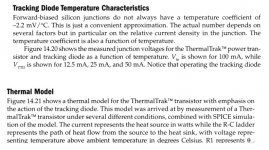
Free downlaod https://linearaudio.net/sites/linearaudio.net/files/v9 jd.pdf see part 2.
Jan
Thanks. I noticed you were asking about the ON Semi thermal traks, I used the Sankens. The difference is that the Sankens have different types of diodes to match the output Darlington Vbe, and also as far as I know in the Sankens the diodes are actually on the same die.
So the ON Semis might be a bit different.
Jan
So the ON Semis might be a bit different.
Jan
From what i was told, I understand the ON Semi TT has a diode inside the case on an insulator. That is, I think equivalent to a diode outside the case on an insulator.
This is why, I personally see no interest in the ON Semi TT.
With such thermal coupling, because of the much larger thermal capacitance of the case compared with the small thermal capacitance of the junctions.... Whatever happens, the temperature difference between the junctions of the bjt and the diode, will be governed by Rth( junction-case) of the Transistor. That is the only parameter one can choose to optimize bias stability.
With the diode really implemented in the same die as the transistor, I would expect a different and worthwhile story.
From what i was told, I understand the ON Semi TT has a diode inside the case on an insulator. That is, I think equivalent to a diode outside the case on an insulator.
This is why, I personally see no interest in the ON Semi TT.
With such thermal coupling, because of the much larger thermal capacitance of the case compared with the small thermal capacitance of the junctions.... Whatever happens, the temperature difference between the junctions of the bjt and the diode, will be governed by Rth( junction-case) of the Transistor. That is the only parameter one can choose to optimize bias stability.
With the diode really implemented in the same die as the transistor, I would expect a different and worthwhile story.
Fully agree. It is nice for long-term thermal stability but not to avoid thermal modulation by the signal level. Even the Sankens which have the diode on the same die (I am told) I see delays of fractions of a second.
Jan
I am looking in detail in your paper.
I suggest you re work with your test gig in figure 12.
This looks perfect for a AC analysis.
BJT power as input, Diode Vf as output, with a ac sweep from near DC to few Hertz.
With such a measured ac transfert you could accurately extract the various Rth and Cth that characterize the thermal system modeled as a linear system.
The same could be done over other BJT with diode attached on case ( or other temp sensor ).
Last edited:
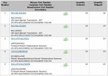
Jan, your article inspired me to plan a project experiment. Just now I bought some Thermal Trak parts (below), enough to make a 200 WPC stereo amp AND also destroy a few devices in thermal testing & characterization. I decided to get the highest-power-rating devices; they were only $0.77 more at Mouser.
The three different temperature sensor ICs ensure that I will become Confucius's "man with two watches, never know what time it is". Bought a few Arduino Mega boards on eBay too; easy interface to the digital-output ICs in line items 3 & 4.
As you well know, initial component purchase is not a guarantee the project will ever get started (or finished).
_
Attachments
If the diode is on the same die, there will be limited electrical isolation between the diode and the transistor.
Even a hybrid with the die on the spreader will have much better thermal tracking than any external device on the heatsink. Only a device sitting directly on the tab will be close
Even a hybrid with the die on the spreader will have much better thermal tracking than any external device on the heatsink. Only a device sitting directly on the tab will be close
Jan, your article inspired me to plan a project experiment. Just now I bought some Thermal Trak parts (below), enough to make a 200 WPC stereo amp AND also destroy a few devices in thermal testing & characterization. I decided to get the highest-power-rating devices; they were only $0.77 more at Mouser.
The three different temperature sensor ICs ensure that I will become Confucius's "man with two watches, never know what time it is". Bought a few Arduino Mega boards on eBay too; easy interface to the digital-output ICs in line items 3 & 4.
As you well know, initial component purchase is not a guarantee the project will ever get started (or finished).
_
Well I do hope the project gets done - it is an intresting area. BTW I have been using LM35's in another project as temp sensors because they are linear in Celcius, with 0C at 0V. Probably also available similarly in Fahrenheit. Makes the sensing circuit a bit simpler.
Edit: I belive Doug Self has written about this subject, concluding, iirc, that a sensor on top of the plastic package of the power device would track die temperature best. Don't remember the details.
Jan
Last edited:
I am looking in detail in your paper.
I suggest you re work with your test gig in figure 12.
This looks perfect for a AC analysis.
BJT power as input, Diode Vf as output, with a ac sweep from near DC to few Hertz.
With such a measured ac transfert you could accurately extract the various Rth and Cth that characterize the thermal system modeled as a linear system.
The same could be done over other BJT with diode attached on case ( or other temp sensor ).
I hear you, but I have dismantled the test jig, and it is unlikely that I will start it up again. But never say never ;-)
Jan
What do you think the isolation is in a transistor with 250volt Vceo ?If the diode is on the same die, there will be limited electrical isolation between the diode and the transistor.
Even a hybrid with the die on the spreader will have much better thermal tracking than any external device on the heatsink. Only a device sitting directly on the tab will be close
Better tracking is yet to be proved. From physics and modeling there is no reason for a better tracking.
If the diode is integrated and not using additional processes like dielectric isolation, the diode will have a hidden parasitic junction to the collector.What do you think the isolation is in a transistor with 250volt Vceo ?
If the diode is a discrete device, mounted on the spreader and encapsulated, the isolation will be limited by the external lead spacing.
In the end junction temperature is not even die temperature
I'm not aware of any power transistor with an intrinsic diode to use as a temperature sensor, it would surely be very expensive to fabricate. Having an insulated diode as close as practical to the transistor die is a better compromise than mounting a diode externally, as Sloan demonstrated in his book.
I modified an existing Leach amplifier to use two of these devices plus two more with a similar diode mounted on top of a conventional non-diode part to gain a full complement of output transistors. Seems very temperature stable in use, and I think the amplifier sounds much better at higher power levels (though that might be due to the use of perforated emitter transistors having a broad linear range, and less the improved thermal tracking). Need to get a full set of Thermal Trak devices for a less kludgy approach.
I modified an existing Leach amplifier to use two of these devices plus two more with a similar diode mounted on top of a conventional non-diode part to gain a full complement of output transistors. Seems very temperature stable in use, and I think the amplifier sounds much better at higher power levels (though that might be due to the use of perforated emitter transistors having a broad linear range, and less the improved thermal tracking). Need to get a full set of Thermal Trak devices for a less kludgy approach.
Not true, there used to be N channel mosfets with a secondary sensor device on the die common source and gate with separate drain. Obviously the package costs a little more but the die will be almost the same as a standard multicell deviceI'm not aware of any power transistor with an intrinsic diode to use as a temperature sensor, it would surely be very expensive to fabricate
- Status
- This old topic is closed. If you want to reopen this topic, contact a moderator using the "Report Post" button.
- Home
- Design & Build
- Parts
- ThermalTrack from ON Semi.