There's the ZDT694 from Diodes Inc in the Mouser catalog.
Good find! The FMB5551 has higher fT and slightly greater ICmax, also at Mouser.
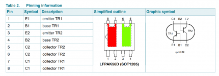
I doubt that the NPN half and the PNP half of PHPT610030NPK have identical Beta or identical VBE. Looking at the datasheet it seems the NPN ("TR1") has higher Beta and the PNP ("TR2") has higher VBE. It also appears that they are two completely separate die, attached to two completely separate die paddles. So the thermal pathway between them is made of epoxy.
_
_
Attachments
In my application: Non identical Vbe between npn and pnp is no trouble because what does matter is vbe_pnp + vbe_npn.
Matching of beta would be better. They are not matched but quite close in the data sheet.
Not the same die with epoxy in between is bad.
What would be a guess estimate for the Rth between dies ?
What's the thermal pathway for junctions heat to reach ambient ?
Am I better with 2 of those duals, than with 4 bjts tied together ?
Last edited:
PHPT610030NPK is dual npn/pnp
PHPT610030NK is dual npn
PHPT610030PK is dual pnp
All 3 are 2 transistors in the same case. Unfortunate, not on the same die, just two transistors glued in the same package.
And...size is 5mm x 5mm. And if a transistor needs some heat extraction, it needs a 20mm x 30mm pad.
ThermalTrack from ON Semi. Is the diode and BJT on the same die ?
I think I read that they are not on the same die.
I do not find technical info about how it temperature tracks, apart from assertions and commercial hypes.
So called ‘thermal trak’ transistors, although effective for stabilizing the bias current long-term, were found to be not effective on the time scale investigated.
https://linearaudio.net/article-detail/2227
I am not after thermal distortion. I am at 20Khz thd.
In Class AB amplifiers, poor bias stability does induce distortion especially when using low quiescent current.
I am after a sneaky side effect of gm doubling; It does induce distortion on high level signals. With poor temperature tracking, the A region goes wider with temperature and that worsen the thd for high level signals.
Biasing is a compromise when looking for a low thd for signals at all amplitudes.
Once you've set what you consider a "best" biais, for your listening taste, you do need biais stability to stay there.
It all boils at, how much is the temperature difference between the junctions of the bjt and the diode when the output stage goes from idling to full power.
Here is why I look for junctions on the same die.
If the diode is not on the same die in a ThermalTrack, I do not need any, I can do as well with standard BJT's.
Last edited:
Somebody is going to have to do some laboratory investigation. Either you, or the author of a book / article / website / comment_post, or a consultant you hire.
Feel free to explore the various options in whichever order you like; maybe you prefer to search around for zero-cost information, before investing €1,99 to buy an article that may or may not be sufficiently beneficial.
Feel free to explore the various options in whichever order you like; maybe you prefer to search around for zero-cost information, before investing €1,99 to buy an article that may or may not be sufficiently beneficial.
I already thought of simple experiments that would tell a lot.
Step a ThermalTrack Transistor from 0 Watt to some Watts and monitor case temperature and diode Vf over time. Monitor the Vbe of the transistor too.
Chart the Vf as a function of temperature ( with case at a steady temperature from various power sttings ).
And here again, I rant that this kind of thing, should be on the data sheets and application notes.
All there is actually from ON Semi, is: We have put a diode in a transistor case.
- Status
- This old topic is closed. If you want to reopen this topic, contact a moderator using the "Report Post" button.
- Home
- Design & Build
- Parts
- Dual BJT 1A