Does anybody have any tips or suggestions on how to create a noninductive load resistor (or low-inductance load resistor) using cheap 10W wirewound resistors in cement block packages?
I am thinking I'll put N of them in parallel (reducing inductance by a factor of N) and then arrange the current paths to be in opposite directions. This will create a mutual inductance between adjacent resistors, and since the currents flow in opposite directions, the effective inductance will be reduced to (L - M) where L is the self inductance and M is the mutual inductance.
I just purchased qty=28 of 10 watt, 56 ohm resistors. I'll put 14 of them in parallel (giving a 4.0 ohm resistor), and connect that in series with another set of 14 ohms in parallel. End-to-end resistance is 8.0 ohms, and inductance is (hopefully) a lot less than (1/14th) the inductance of a single resistor.
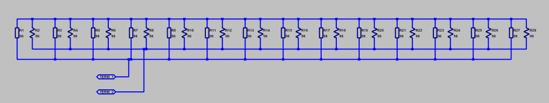
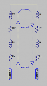
Figure 1 below shows a schematic of my connection. Figure 2 illustrates the mutual inductance between a pair of adjacent resistors. Of course it's a distributed system but for compactness I've drawn it as two "lumps".
What do you think of the idea? Is there a far, far better way to get low end-to-end inductance when using wirewound resistors?
Thanks for reading!
_
I am thinking I'll put N of them in parallel (reducing inductance by a factor of N) and then arrange the current paths to be in opposite directions. This will create a mutual inductance between adjacent resistors, and since the currents flow in opposite directions, the effective inductance will be reduced to (L - M) where L is the self inductance and M is the mutual inductance.
I just purchased qty=28 of 10 watt, 56 ohm resistors. I'll put 14 of them in parallel (giving a 4.0 ohm resistor), and connect that in series with another set of 14 ohms in parallel. End-to-end resistance is 8.0 ohms, and inductance is (hopefully) a lot less than (1/14th) the inductance of a single resistor.
Figure 1 below shows a schematic of my connection. Figure 2 illustrates the mutual inductance between a pair of adjacent resistors. Of course it's a distributed system but for compactness I've drawn it as two "lumps".
What do you think of the idea? Is there a far, far better way to get low end-to-end inductance when using wirewound resistors?
Thanks for reading!
_
Attachments
Mutual inductance will be small, so hardly worth worrying about. What you actually need to do (in addition to paralleling) is to ensure that the net current loop has zero area. Jneutron is the expert on this, as he does things like this for a living.
By the way, why do you want a non-inductive load? Real speakers are not non-inductive.
By the way, why do you want a non-inductive load? Real speakers are not non-inductive.
It won't work well, for the reason given by DF: the relatively small winding is enclosed in a relatively large ceramic casing, meaning the lines of field will reconnect inside, no matter what you do outside.
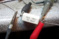
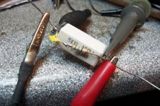
If you wanted to follow this "physical" route, your best option would be to wrap the resistors inside copper (or aluminum) foil, to make a short-circuited turn (and it would improve the thermal conductivity, which is important, because packing together many dissipation sources will be detrimental), but there is a simpler, and more effective option: compensating for the parasitic inductance is relatively easy, as the pics below show:
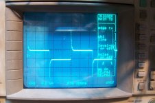
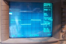
A 15Ω resistor is fed by a squarewave from a 50Ω function generator; the effect of the inductance is visible through the differentiating of the waveform.
A simple series RC network (16Ω + 2.7nF) placed in parallel is sufficient to provide a vast improvement. Note that this is a quick and dirty fix, with a E24 resistor value and a X7R ceramic cap.
With some tweaking, precision components (and perhaps a higher order network), the compensation could be perfect
If you wanted to follow this "physical" route, your best option would be to wrap the resistors inside copper (or aluminum) foil, to make a short-circuited turn (and it would improve the thermal conductivity, which is important, because packing together many dissipation sources will be detrimental), but there is a simpler, and more effective option: compensating for the parasitic inductance is relatively easy, as the pics below show:
A 15Ω resistor is fed by a squarewave from a 50Ω function generator; the effect of the inductance is visible through the differentiating of the waveform.
A simple series RC network (16Ω + 2.7nF) placed in parallel is sufficient to provide a vast improvement. Note that this is a quick and dirty fix, with a E24 resistor value and a X7R ceramic cap.
With some tweaking, precision components (and perhaps a higher order network), the compensation could be perfect
Attachments
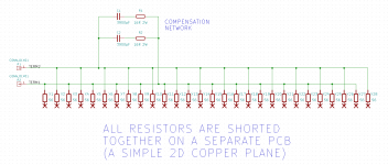
I got a PM suggesting that the circuit schematic is fine BUT it shows the resistors laid out in a 1-dimensional array. The suggestion: it's FAR better to lay out the resistors as a 2-dimensional array. Thus the Term_1, Term_2, and MidPoint nodes become planes rather than linear wires, and the resistors are mounted "cordwood" style between two copper clad PCBs. Planes == PCB layers. Thanks a lot!
In order to benefit from elaborate or exotic layout schemes, you will need to start from low inductance components in the first place, like thick-film power resistors, otherwise it will act as icing on a cake: a few grams of very visible candy on a kg-size cake (or a fraction of an ounce of icing on a pound-size cake if you prefer).
If a continuous HF power rating is not required (which is normally the case for an audio amplifier, unless it oscillates), a small equalization network is the sensible solution (and it can also compensate for the wiring inductance).
Having a lower initial parasitic inductance is in principle a good thing, since compensations and equalizations are never perfect, but here we are talking about percents, or maybe tens of of percents at most, and bothering about such a small fraction is probably not worth the effort
Built it and verified its lack of inductance
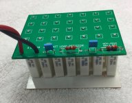
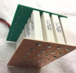
I was in a vile and ugly mood on Wednesday, November 10th, so to do something productive I decided to lay this out as a PCB and have it built at whichever fab gave the lowest price quote on pcbshopper.com . The winner was "Maker Studio" who charged me $15.56 for ten (dual sided) PCBs including shipping to California. Finished boards arrived five weeks later. And here is the end result.
Image 1 shows the schematic. There are three "planes" on two PCBs. The first two planes are on the PCB I sent to China for fabrication; the third plane is an un-etched, un-patterned piece of raw PCB stock; it's simply a shorting plane. The large X terminals on the bottom of each resistor, connect to this third plane.
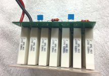
Resistors are laid out "Cordwood" style, arranged in a checkerboard pattern. Resistors which fall in red checkerboard squares, have their top terminal soldered to plane TERM1. Resistors which fall in black checkerboard squares, have their top terminal soldered to plane TERM2.
A bit of twiddling around with a capacitance substitution box showed that the inductance of these wirewound resistors could be nullified using a (8R series 7.9nF) compensator. Thanks to Elvee for the suggestion. It is implemented as two parallel networks, for better power handling capability. I wanted a large margin of safety even when 75 volt, 100 kilohertz sinewaves are applied.
Scope photos of the array of 28 resistors, with and without the compensators, are shown in images 2 and 3. With no compensation, square wave input produces huge overshoot due to the series inductance of the wirewound resistors. After compensation is applied, the square wave response is acceptably good.
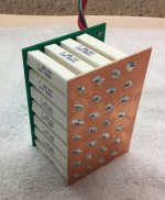
Photos of the first article appear in images 4-7.
I've got a couple spare boards which I'm willing to give away for free as long as you pay for the envelope and postage. Patterned PCB only; you have to source and cut and drill the plane3 unetched bare copper board yourself. Send me a PM if interested.
By the way it was a fun little brain-teaser to figure out how to thread a 4 x 7 array of resistor leads through a pair of solid & inflexible PCBs. Think about it for a minute -- it's not a completely trivial task.
I was in a vile and ugly mood on Wednesday, November 10th, so to do something productive I decided to lay this out as a PCB and have it built at whichever fab gave the lowest price quote on pcbshopper.com . The winner was "Maker Studio" who charged me $15.56 for ten (dual sided) PCBs including shipping to California. Finished boards arrived five weeks later. And here is the end result.
Image 1 shows the schematic. There are three "planes" on two PCBs. The first two planes are on the PCB I sent to China for fabrication; the third plane is an un-etched, un-patterned piece of raw PCB stock; it's simply a shorting plane. The large X terminals on the bottom of each resistor, connect to this third plane.
Resistors are laid out "Cordwood" style, arranged in a checkerboard pattern. Resistors which fall in red checkerboard squares, have their top terminal soldered to plane TERM1. Resistors which fall in black checkerboard squares, have their top terminal soldered to plane TERM2.
A bit of twiddling around with a capacitance substitution box showed that the inductance of these wirewound resistors could be nullified using a (8R series 7.9nF) compensator. Thanks to Elvee for the suggestion. It is implemented as two parallel networks, for better power handling capability. I wanted a large margin of safety even when 75 volt, 100 kilohertz sinewaves are applied.
Scope photos of the array of 28 resistors, with and without the compensators, are shown in images 2 and 3. With no compensation, square wave input produces huge overshoot due to the series inductance of the wirewound resistors. After compensation is applied, the square wave response is acceptably good.
Photos of the first article appear in images 4-7.
I've got a couple spare boards which I'm willing to give away for free as long as you pay for the envelope and postage. Patterned PCB only; you have to source and cut and drill the plane3 unetched bare copper board yourself. Send me a PM if interested.
By the way it was a fun little brain-teaser to figure out how to thread a 4 x 7 array of resistor leads through a pair of solid & inflexible PCBs. Think about it for a minute -- it's not a completely trivial task.
Attachments
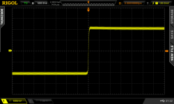
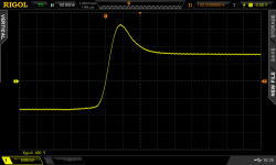
Yeah you are right. I should have laid out a jumper or other mechanism to make it easier to enable/disable the compensator AFTER it is soldered into the PCB. Today I'm stuck with whatever scope pix I happened to take (and not discard!) before soldering in the compensator parts. Had I included an enable/disable jumper, I could perform a full suite of with/without comparisons at different sweep rates, different amplitudes, and even with different arbitrary waveform inputs. Oh well, that's what Rev.B might include.Cute, but 50nS/div before and 500nS/div after!")
By the way, Pierre-Simon Laplace says that when the compensation is exactly right, R=sqrt(L/C). Since we know both R and C we can calculate L: it is 506 nanohenries. Parallel resistors + low inductance planar traces + (slight) cancellation due to mutual inductive coupling, has reduced the net inductance quite delightfully well. The compensator doesn't have to work very hard at all, which means I don't need ridiculously high ripple current ratings on the capacitors or huge wattage ratings on the 16R resistors. Nice.
Thanks for the kind words!
Last edited:

Mark, I recon that you are aware there are many different types of wirewound resistors, some winding techniques more exotic than others to minimize stray LC.
Nonetheless, your end results with the Zobel looks great, Merry Christmas.
https://en.wikipedia.org/wiki/Ayrton-Perry_winding
Nonetheless, your end results with the Zobel looks great, Merry Christmas.
https://en.wikipedia.org/wiki/Ayrton-Perry_winding
I used 28 of these wirewound resistors at $0.36 each, plus a $1.50 PCB and $0.50 worth of compensator components: $12.08 total cost for a noninductive 150 watt 8.0 ohm resistor.
The only Ayrton-Perry resistors I'm able to find at distributors, are the Vishay "NH" series of 250W resistors which sell for $202 per piece and the Vishay "MRA" series which sell for $4.35 per 10 watt resistor
The only Ayrton-Perry resistors I'm able to find at distributors, are the Vishay "NH" series of 250W resistors which sell for $202 per piece and the Vishay "MRA" series which sell for $4.35 per 10 watt resistor
I found that using 45 off 20r 5W radial metal oxide in ceramic cases in a series parallel combination to arrive at a 225W 4r0 was much cheaper and had a lot more thermal mass than anything else at a reasonable cost. I assembled four off 4r0 to give me lots of combinations.
The high thermal mass implies low temperature variation for low duty cycle testing, like 2seconds on @ 100W and 28 seconds off, before the next cycle.
I will need to try the with Zobel and without Zobel for a square wave test and see how it performs.
The high thermal mass implies low temperature variation for low duty cycle testing, like 2seconds on @ 100W and 28 seconds off, before the next cycle.
I will need to try the with Zobel and without Zobel for a square wave test and see how it performs.
Hi.
Or you can buy non-inductive dummy load from Part Express.
https://www.parts-express.com/Search.aspx?keyword=dummy load&sitesearch=true
Or you can buy non-inductive dummy load from Part Express.
https://www.parts-express.com/Search.aspx?keyword=dummy load&sitesearch=true
Hi.
Or you can buy non-inductive dummy load from Part Express.
https://www.parts-express.com/Search.aspx?keyword=dummy load&sitesearch=true
https://www.parts-express.com/8-ohm-200w-non-inductive-dummy-load-resistor--019-030
The Parts Express 200 W units looks similar to the ones measured in the video below.
https://www.youtube.com/watch?v=5hRwIRpxc0Y
In this video the two 8 Ohm units measured around 2,9 uH each.
- Status
- Not open for further replies.
- Home
- Design & Build
- Parts
- Building my own noninductive 8R 150W load using wire wound resistors