Hmmm, I applied a 1.0000 kHz square wave input when making the measurements shown in post #38. Are you saying that if I instead apply a 3.14159 kHz square wave (or a 100 kHz square wave) and make the measurements again, the output this time will exhibit overshoot (or undershoot) ??
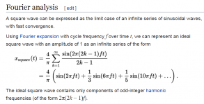
Interesting screengrab from Wikipedia attached below.
~
Interesting screengrab from Wikipedia attached below.
~
Attachments
Last edited:
Inductive cancellation only occurs at a specific frequency.
It's perfect compensation, do the math.
The impedance of the two branches in parallel is : ( R + 1/sC ) // ( R +sL )
= ( R + 1/sC ) x ( R +sL ) / ( ( R + 1/sC ) + ( R +sL ) )
= ( R + s ( L + RCE2 ) + sE2 LRC ) / ( 1+ s2RC + sE2 LC )
= R x ( 1 + s ( L/R + RC ) + sE2 LC ) / ( 1+ s2RC + sE2 LC )
=R provided that L/R = RC
Last edited:
This is complex frequency domain circuit analysis, but you can
simulate the circuit if the algebra isn't good enough.
The impedance of the two branches in parallel is :
( R + 1/sC ) // ( R +sL )
Since A // B = AB/(A+B) we have:
= ( R + 1/sC ) x ( R +sL ) / ( ( R + 1/sC ) + ( R +sL ) )
Gather like terms in the numerator and denominator
and multiply by sC/sC to clear negative powers of s:
= ( R + s ( L + RCE2 ) + sE2 LRC ) / ( 1+ s2RC + sE2 LC )
Pull out a factor of R in the numerator:
= R x ( 1 + s ( L/R + RC ) + sE2 LC ) / ( 1+ s2RC + sE2 LC )
Comparing like powers of s in the numerator and denominator,
the zero order and second order terms of s are the same, and
we see that the linear s terms can be the same if L/R = RC
=R provided that L/R = RC
Last edited:
I asked you for RIGHT maths.It's complex frequency domain circuit analysis, but you can simulate the circuit if the algebra isn't good enough.
mchamblin, what is wrong with rayma's math? It appears correct and nicely explained.
it is ok in the first 2 lines, next it is unclear, wrong I presume.
What is that E2 ?
AND and multiply by sC/sC
That represents a square term, sE2 = s²
(where E = exponential).
Likewise, CE2 = C²
The text editor here seems not to support such characters as s²
Multiplying the ratio of the two quadratics by sC/sC
clears out all 1/s terms without changing the value
of the ratio of the quadratics, since sC/sC =1.
It makes the algebra a little easier.
Comparing like powers of s in the impedance determines
any constraints, since each term of the quadratics must
be the same for the quadratics to cancel out, leaving R.
Last edited:
I was just thinking how I might do this if needs must and in a hurry. Perhaps water loaded with a conductive substance would serve me well enough. One thought did come to me. A Bosch Half Moon cooker element is split half way. If my memory is right if the full circuit is 32R measured ( it might rise a bit when hot ). I assume the split is for a 115 V version. If using the split end with the other ends shorted you will have at least 150 watts at 8R. It should be low inductance as the hoops are wide. I question if we need zero inductance as no real load is. My old Magnepan's claim a pure resistive load. The Bosch element should be no worse or better.
High Quality Replacement Half Moon Fan Oven Element 1700W 230V Fits Bosch , Neff | eBay
High Quality Replacement Half Moon Fan Oven Element 1700W 230V Fits Bosch , Neff | eBay
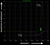
Inductive cancellation only occurs at a specific frequency.
With: L/C = R*R, the impedance is R at any frequency.
By the way, Pierre-Simon Laplace says that when the compensation is exactly right, R=sqrt(L/C).
Last edited:
It's too bad you didn't read post #8 before boldly stating "Inductive cancellation only occurs at a specific frequency.". It's also too bad you didn't attempt to confirm or refute your bold statement by performing a circuit simulation; that might have avoided some embarrassment. See arrowhead on figure attached.
~
~
Attachments
It would be nice if you apologized to member rayma for your lecturing tone. It would be nice if you acknowledged that member rayma proved the final result and you misunderstood his proof. It would be nice if you vowed to double check and reconfirm yourself, before making similarly bold statements in the future.
It would be nice if you apologized to member rayma for your lecturing tone.
No problem, these methods can be puzzling at first glance.
Back in the 70s at the U of Illinois, in our linear active circuits class,
the prof used the floating admittance matrix method exclusively.
At first, both Tom Holman and I were having some difficulties with it,
but after working things out from first principles all became clear, and
it was great to be able to write down the circuit equations by inspection.
Last edited:
It may be easier for some to use the simpler 'all parallel' configuration using single sided plane PCB. The doubt is whether the self inductance of a 56 ohm is significantly different from say 28x8=224 or 220 ohm part, although the RC compensation technique would manage any difference if the test equipment and desire was there to make the load 'ideal' well beyond a MHz.
- Status
- Not open for further replies.
- Home
- Design & Build
- Parts
- Building my own noninductive 8R 150W load using wire wound resistors