Ok, so now I'm in analysis paralysis.
Am I decoupling the supplies, V+ and V- or decoupling the inverting and non-inverting inputs? I've read a few datasheets and looked at lots of circuits but can't tell definitively (usually the details of V+ and V- are omitted, and the caps attached to the +/- inputs could be a part of the circuit design, not decoupling).
I'm trying to figure this out to learn (best way), but I do need and much appreciate your advice.
Missed this comment - parts are from digikey so I'm not concerned about fakes.
Ah - so I desolder all pins, bend pin 8 out, solder the other 7 back in, attach resist between pin 8 and hole, measure. That sounds feasible for me.
Buying from a recognised supplier is the best way... digikey should be fine... but the devices should still be warm (they shouldn't be cold).
For desoldering, its just pin 8, leave all the others soldered, and then carefully solder a 1 ohm to the board and the other end to the free unsoldered pin. All done in less time than it takes to type this. Honest
")
Decoupling refers to the voltage supplies on pin 8 and pin 4. I'm sure you will see small caps from each of those pins to ground if you look near each chip. That should be sufficient on a unit like this. You could if you wanted add a small (say 4.7uf 63v) electrolytic soldered in series with a 1 or 2.2 ohm 0.25 watt resistor across pins 4 and 8 of each opamp. You shouldn't need it for the 5532 and TL072 though.
I swapped about a dozen tl072 for lm4562 in my 30+ year old preamp.
After reading and reading and re-reading the service manual and opamps datasheets, I concluded I could just swap them. Now I've read in some other threads about decoupling caps needed.
It works and sounds fine after the swap.
So my question is, am I ok and safe (literally) electrically?
-david
I did not read beyond the first page. On top of the other concerns given, TL072 is a jFET input that has high input impedance, it works with higher resistance signal path, LM4562 is BJT input that draw a lot more current, you really need to look at the schematic to verify that this does not present a problem.
LM4562 is a whole lot faster than TL072, but if you said it sounds OK, I guess you don't have oscillation problem.
For desoldering, its just pin 8, leave all the others soldered, and then carefully solder a 1 ohm to the board and the other end to the free unsoldered pin. All done in less time than it takes to type this. Honest
You must be a very slow typer
Anyway a got the leg bent out, and put together a franken-resistor (4 x 4.7ohm). I may have mangled the leg too much to resolder, but that's why you buy extras
So here are the results:
R=1.25 ohm (measured)
V=12.19mV (measured)
That leads to 9.8mA (approx).
Should I be comparing that to the quiescent current in the datasheet? If so, then it's good - datasheet says 10mA is typical.
I won't resolder and close it up just yet.
10ma is bang on the money. They must be warm at that because 0.01amps times the total supply voltage of 34 volts is 0.34 watts. Maybe your fingers need a bit more gain
You should try solder braid if you intend working much on this kind of gear. One second per leg tops to desolder one of these little suckers.
You should try solder braid if you intend working much on this kind of gear. One second per leg tops to desolder one of these little suckers.
10ma is bang on the money. They must be warm at that because 0.01amps times the total supply voltage of 34 volts is 0.34 watts. Maybe your fingers need a bit more gain
You should try solder braid if you intend working much on this kind of gear. One second per leg tops to desolder one of these little suckers.
For my own edification, is the quiescent current the benchmark spec I should be comparing it to? The measured numbers didn't seem to change based on volume or other factors.
That is good news.
I Using tweezers to bend and pull the leg out of the hole was the tricky part.
Ah... I see. I meant to just solder the resistor to the free bit of leg poking through the hole (lol, that sounds a bit risqué).
Yes, the current won't change much under signal conditions. Even if you had a volt or so signal it will probably be working into impedances around the 10k mark so very little change... and its a dynamic quantity which the meter wont show accurately.
@Mooly - I just saw your other thread on swapping opamps. Wish I had found that earlier, it is very good.
I'm going with jean-paul's suggestion of a Wima cap between +/- voltage supplies. It's just more space efficient than your suggestion of a cap and resistor in series.
Digikey doesn't carry Wima so I'll get an equivalent. I'm also going to pick up a cheap oscope probe.
Anyone have any other suggestions for my cart?
The Wima's will be fine. Scope probes don't come cheap these days and I wouldn't know what to recommend without trawling the catalogues tbh. You do need a divider type (10:1) preferably switchable as that gives the option of using the attenuated setting which gives low capacitance loading to the circuit under test.
I suspect you are probably looking for something like this as a minimum,
76-109 - TENMA - PROBE, O'SCOPE 60MHZ | CPC UK
I suspect you are probably looking for something like this as a minimum,
76-109 - TENMA - PROBE, O'SCOPE 60MHZ | CPC UK
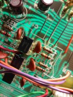
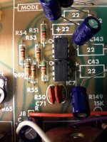
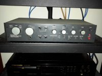
Hi all. I've finally got it all in place, thanks for your help!
I'd like to say the mids sound more airy and the bass is...different. I can't say that for sure. But I can say definitely that I had fun making the changes, learned a lot, and that's a large part of the diy experience for me.
Unfortunately I forgot to take some nice pix of all the changes. I do have some though.
Attachments
My thoughts, exactly. I have found many counterfeit LM4562NA and RC4558P available. Be sure you are buying genuine/authentic OpAmps.
That's good... except... 4562's should run noticeably warm (as in easily detectably warm) if you place the back of a finger on them. If they really are as cool to the point of not being able to tell, then I'm suspicious that they might not be genuine devices.
Amazingly, yes. All along the board you will find knockoffs. I have built my business selling, only, authentic, genuine brand name electronic components. Thats how much these fakes have effected my projects.
RC4558P counterfit? They are only 25 cents each from RS. I thought these were the ones that get remarked as something more exotic
Amazingly, yes. All along the board you will find knockoffs. I have built my business selling, only, authentic, genuine brand name electronic components. Thats how much these fakes have effected my projects.
How do you test for fakes? Your prices (lm4562na) are lower than digikey, which normally would send up red flags. If it's easy I'd like to test one of mine, I have extras.
I try to keep my pricing cost effective and respectable, since I supply many hobbyists and DIYers which I can directly associate with.
With respect to testing, manufacturer datasheet tolerances are my key reference. I look at Intermodulation distortion, THD, SINAD, noise floor, CMRR, frequency response, full spectral analysis, thermal properties under variances of supply voltages... and I can go on and on.....
There are many cases where you can pick out fakes by simply comparing Silkscreen differentials. For instance, many PTC PT2399 IC fakes are silkscreened with "DTC" as oppose to "PTC" cleverly.
How do you test for fakes? Your prices (lm4562na) are lower than digikey, which normally would send up red flags. If it's easy I'd like to test one of mine, I have extras.
- Status
- This old topic is closed. If you want to reopen this topic, contact a moderator using the "Report Post" button.
- Home
- Design & Build
- Parts
- I substituted some opamps, now I'm nervous