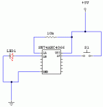
I was playing with a SN74AHC4066 quadruple CMOS switch, and got some interesting results (at least to me  ). Anyways hoping someone could explain this to me.
I did a simple wire up like in the picture below. The 1A & 1B are the input/output and the 1C is the controll. Anways when I apply power to the circuit the LED bairly, bairly turns on, and when I press the momentary switch on the control to activate the switch the LED gets about twice as bright, still pretty DIM, but more seeable.
So my question is why does the LED light up when the switch is inactive? The only thing I can thing of is that I was sending a DC power through the switch and since it uses transistors to replicate a mechanical switch it doesn't handle the DC to well, like an op-amp.
Also this particular switch has an advertised R(on) of ~75ohms, while some of the other "high quality" CMOS switches have R(on) ratings of 5-0.5 ohms. WIll this make a big difference? I know some have ratings as high as 200ohms or more, which probably would make a difference in distortion.
Thanks
-David
Attachments
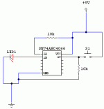
1. Reason that the LED is dimly lit on power up because if you read the data sheet carefully, it says that the switch is only turned off (in high impedance state) when the control input, 1c, is at the same voltage as the GND pin. So connect a resistor (I think 10K would do) across the 1c pin and ground. There's a CMOS rule that says to never leave an input unterminated. I'd also terminate all the other unused pins in that chip.
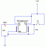
2. I think the reason why the LED is not bright when the switch is pressed is because of 10K source resistor you've used. This only allows 500uA to the LED. I think that's too little current.
2. I think the reason why the LED is not bright when the switch is pressed is because of 10K source resistor you've used. This only allows 500uA to the LED. I think that's too little current.
You can say that again 
What do you mean by this? Like connect to ground?
Also is this what you mean by c to ground?
Also thanks for your help
There's a CMOS rule that says to never leave an input unterminated. I'd also terminate all the other unused pins in that chip.
What do you mean by this? Like connect to ground?
Also is this what you mean by c to ground?
Also thanks for your help
Attachments
Hybrid fourdoor said:You can say that again
What do you mean by this? Like connect to ground?
Also is this what you mean by c to ground?
Also thanks for your help
Sorry. I hit the "back" button in IE and it post the article again without my wish.
Yes, connect all the other three control inputs 2c,3c,and 4c (but NOT the unused switches) to ground. I don't think the switches need termination. As a matter of fact, I think it's bad to connect more than one switches to a common point (says the data sheet)
Yes, you've got the correct connection for 1c.
If you want the LED to go brighter, you can lower the 10K source resistor, but be careful not to exceed the limit of the pin (data sheet says 25mA absolute maximum. Note "absolute maximum"
 )
)bikejog said:
Yes, connect all the other three control inputs 2c,3c,and 4c (but NOT the unused switches) to ground. I don't think the switches need termination. As a matter of fact, I think it's bad to connect more than one switches to a common point (says the data sheet)
Told you to wait for confirmation
So don't connect all the inputs to the GND. My bad.
As for the 680 resistor on the LED, it works well for me with CDxxxx CMOS suplied in 12v... Might be different with 74xxxxs...
- Status
- This old topic is closed. If you want to reopen this topic, contact a moderator using the "Report Post" button.
- Home
- Design & Build
- Parts
- Help me understand this CMOS switch


 ).
).