
Hello! I need some help picking out parts for this schematic: It is based on the BH7824FVM amplifier.)
The recommended component values are in an application circuit in the product data sheet page 3, linked by DIgikey.
Use a metal film resistors and film capacitors, except the largest one is an electrolytic type.
The recommended component values are in an application circuit in the product data sheet page 3, linked by DIgikey.
Use a metal film resistors and film capacitors, except the largest one is an electrolytic type.
The recommended component values are in an application circuit in the product data sheet page 3, linked by DIgikey.
Use a metal film resistors and film capacitors, except the largest one is an electrolytic type.
Thank you!
")
I got some questions. What does these means?
1.

2.

3.

4.

5.

And where is input sound, input power and output sound?
Thank you!
1/ A variable capacitor. You wont find those in audio stuff. They are for tuning RF circuits (typically)
2/ A 0.1uf (microfarad) non polarised capacitor such as a film or ceramic type.
3/ A polarised capacitor such as an electrolytic.
4/ An AC voltage source.
5/ Indeterminate. I would assume it to be a DC voltage source.
The power supply to operate the circuit goes to pins 6 and 7. Pin 6 is shown as the positive supply. The input connects to where it says sp in (L & R). The input ground is the same as the power supply ground (pin 7).
You will need to look up what to do with pin 1. It may well be normal to leave it floating and only apply a voltage (or ground it) to put the amp in a low power shutdown state.
1/ A variable capacitor. You wont find those in audio stuff. They are for tuning RF circuits (typically)
2/ A 0.1uf (microfarad) non polarised capacitor such as a film or ceramic type.
3/ A polarised capacitor such as an electrolytic.
4/ An AC voltage source.
5/ Indeterminate. I would assume it to be a DC voltage source.
The power supply to operate the circuit goes to pins 6 and 7. Pin 6 is shown as the positive supply. The input connects to where it says sp in (L & R). The input ground is the same as the power supply ground (pin 7).
You will need to look up what to do with pin 1. It may well be normal to leave it floating and only apply a voltage (or ground it) to put the amp in a low power shutdown state.
Thank you so much! I will try to do the rest my myself. I my ask my questions.

This is ground, right?
Lol, wrong
It means a chassis ground that isn't necessarily connected to a mains ground. It is a subtle difference. Ground symbols tend to get misused... we think we know what they mean and then realise we used the wrong one.
Lol, wrong
It means a chassis ground that isn't necessarily connected to a mains ground. It is a subtle difference. Ground symbols tend to get misused... we think we know what they mean and then realise we used the wrong one.
Haha, okay so i will connect it to what every my ground is on my board?
Hang on... the first resistor I looked at in your list comes up as an SMD (surface mount device). Is that what you want ?
Also, is the IC available as a conventional DIP package ? I'm not so sure it is. Do you realise how small that device is. Its about 3mm by 2mm.
Also I made an error in your list of symbols. #1 is actually meaning a variable DC voltage that presumably causes the IC to 'sleep' at some preset value. The variable capacitor symbol (actually a trimmer) is the same but both lines are the same size.
https://www.google.co.uk/search?q=v...=X&ei=KOXoVI32JoasUbDAg4gC&sqi=2&ved=0CC0Q7Ak
Hang on... the first resistor I looked at in your list comes up as an SMD (surface mount device). Is that what you want ?
Also, is the IC available as a conventional DIP package ? I'm not so sure it is. Do you realise how small that device is. Its about 3mm by 2mm.
Also I made an error in your list of symbols. #1 is actually meaning a variable DC voltage that presumably causes the IC to 'sleep' at some preset value. The variable capacitor symbol (actually a trimmer) is the same but both lines are the same size.
https://www.google.co.uk/search?q=v...=X&ei=KOXoVI32JoasUbDAg4gC&sqi=2&ved=0CC0Q7Ak
Can you help me complete my list because i'm a newbie and will just pick wrong parts.
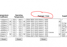
I haven't time to pick them all out for you but you can be sure to get it right by deciding first of all what size part you want.
Scroll down to where it says packages and decide what resistorcap size you need,
Surface-mount technology - Wikipedia, the free encyclopedia
Use Digikeys filters to show what's available. Put your value and package size in.
The 600 ohm on the diagram is just to terminate the input. You may not need it or more typically a value of say 100k would be used. The 8 ohm is the speaker. The 100uf needs to be a small electrolytic (smd if you want). The 0.1uf can be either film or ceramic.
but you can be sure to get it right by deciding first of all what size part you want.Scroll down to where it says packages and decide what resistorcap size you need,
Surface-mount technology - Wikipedia, the free encyclopedia
Use Digikeys filters to show what's available. Put your value and package size in.
The 600 ohm on the diagram is just to terminate the input. You may not need it or more typically a value of say 100k would be used. The 8 ohm is the speaker. The 100uf needs to be a small electrolytic (smd if you want). The 0.1uf can be either film or ceramic.
Attachments
5/ Indeterminate. I would assume it to be a DC voltage source.
Given that that symbol comes from the section "Measurement circuit" on page 3 of this datasheet, and it's connected to the output, I'd say it's a voltmeter.
You work out the power dissipation of the resistors by looking at worst case voltage across them and calculate accordingly. None of the resistors (not counting the 8 ohm speaker) will need power ratings over 0.1watt (its actually a lot less than that). Caps are chosen on type and voltage rating.
- Status
- This old topic is closed. If you want to reopen this topic, contact a moderator using the "Report Post" button.
- Home
- Design & Build
- Parts
- Picking out parts for this schematic