I am new to audio and electronics and made my first piece as a gift for my friend.
It is an audio mixer and amp in an altoids case.
I used this as a guide to have two jacks to to a single 3.5mm output.
Altoids Tin 1/8" Stereo Mixer
It goes to this mini amp.
Amazon.com: DROK Ultra Small Mini 5V Audio Amplifier Digital Ampli Board Support USB Power Two Channel Stereo Amp 3W+3W for Portable Speaker Headphones Headset: Electronics
That is powered by 2 AA batteries.
From there it goes to the output jack. It mixes the audio fine, and their volume is adjusted via the devices that input the sound. The problem is when I turn on the amp you hear a hum in the back ground. I want to clear this up so that my friend can enjoy pod casts while he plays games. I found one review on the amazon page for the amp that says a power supply might cause noise, and a 100uf cap can resolve it. I picked up a 100uf capacitor from radio shack and tested it on the positive side of the power but the amp does not turn on with the cap in line.
If someone could suggest an inexpensive part that I can add to this mixer to reduce or remove the hum I would appreciate it. If this is in the wrong section I apologize and please move to the proper forum.
Thanks. BTW: Here is the mixer.
An externally hosted image should be here but it was not working when we last tested it.
If you put a cap inline with the positive wire it will block the DC! You should have put it across positive and negative.
Considering I am very new to this, I am just going to clarify.
So I would put one end of the cap in line with the positive wire, then the other end of the cap in line with the negative wire. The amplifier can not have its poles reversed, so I want to make sure before I fry something. Does the cap direction matter?
thanks.
Hi Coldiron,
")
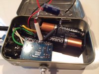
Open it up and post a good picture of the inside .....
NS
Here is a pic from the inside. Its all sort of compact so some things might be hard to see unless I take things apart.
An externally hosted image should be here but it was not working when we last tested it.
Coldiron-
The cap should be soldered between the red and black wires where they attach to the circuit board. These are the supply pins, as noted earlier. Make sure you place the negative leg of the capacitor to the black wire and the other to the red. The capacitor will have a band of arrows pointing toward the negative leg. Make sure you get this right. Remove the batteries before soldering. Then bend the caps leads if needed to get it out of the way.
The cap should be soldered between the red and black wires where they attach to the circuit board. These are the supply pins, as noted earlier. Make sure you place the negative leg of the capacitor to the black wire and the other to the red. The capacitor will have a band of arrows pointing toward the negative leg. Make sure you get this right. Remove the batteries before soldering. Then bend the caps leads if needed to get it out of the way.
Thanks for the reply gibbman.
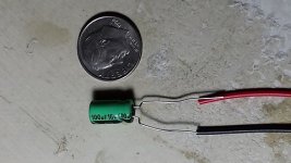
Over the weekend I researched some and did a test where I put the cap between the + & -. I guess it is called a Decoupling capacitor. My test did not power the device and caused it to make a weird noise as if it is trying to power on. I get a similar noise if I twist power wires on this amp and do not salder them.
Here is a picture. I will remove the test piece and put it at the points on the board instead of inline and see if that works.
Thanks.
Attachments
Coldiron, a couple of questions:
Your amp board calls for 5V, it seems you are giving it ~3 (2 AA)?
You show the capacitor installed with the right polarity, you would want to go from pin to pin on the board, you can find much smaller caps for this if indeed you get it working with the one you have spliced in. Did the amp ever work correctly as just an amp?
Attachments
The amp did work correctly up to a certain volume. When you turn it too high it stutters and ticks. Seems to work well from low to mid. The literature I read on it claims the amp can operate from a 3v range. I just wanted the amp in there to get it loud enough to hear vs how quiet it was with just the mixer. I hooked up the cap and it seems the hiss is quieter, which is good enough. I need to take a few points apart and redo them since I redid some of them trying to trouble shoot.
Thanks.
Thanks.

I finally got this done. I am going to test it for a week before I give it to my friend just to make sure everything is durable. I ended up getting a 2nd board. I more or less ruined it from troubleshooting. I thought I could keep things more tidy but I had to redo a lot of wires due to flexing things too much when taking parts in and out for testing. I kept breaking terminals on the jacks, which caused me to break the diodes when taking those out to fix. I think everything is solid now. I found this board is very sensitive to being wired perfect. If you have a loose connector on anything, it will not work right. One hurdle was the output jack was grounding and kept screwing with it. I made a few sleeves but nothing really worked so I used epoxy to make a range between the metal and it seems great now. Lastly, it does work at a higher range now. It does seem to not always cope well on its loudest settings, but for the most part it does what I want it to. Thanks for the help on this board. Now to 3d print a cover and call it a night.
An externally hosted image should be here but it was not working when we last tested it.
- Status
- This old topic is closed. If you want to reopen this topic, contact a moderator using the "Report Post" button.
- Home
- Design & Build
- Parts
- Part to remove hum from mini amp mixer