This has opened a new can of worms.
I've rechecked the measurements and get the same result. Iq was checked by inserting a low value resistor in the plus supply and deriving the current from the measured volt drop. As a double check I add the meter in series with the supply. Same slightly high Iq.
Could the chip be oscillating on the breadboard I used ? Well a 100Mhz scope says no.
At this point I touch the scope probe on the + input pin and Iq falls. Huh !
The long and short of it all seems to be that any resistor over around 470k causes the chip to 'latch' when the supply is turned on. The act of just touching a meter lead or scope probe on the pins of the chip 'unlatches' it. Use 470k or less and no latching occurs.
When in the 'latched' state the output pin is stuck to the negative rail.
Both opamps within the package seem to behave independently and you can have one latched and one not.
I tried other LM4562's with the same result.
Switching the supply on instantly or ramping it slowly makes no difference. Adding decoupling also makes no difference.
Open to offers on that one")
I would say that once 'unlatched' the offset voltages measured were correct, and Iq then comes in at bang on 10ma.
I've rechecked the measurements and get the same result. Iq was checked by inserting a low value resistor in the plus supply and deriving the current from the measured volt drop. As a double check I add the meter in series with the supply. Same slightly high Iq.
Could the chip be oscillating on the breadboard I used ? Well a 100Mhz scope says no.
At this point I touch the scope probe on the + input pin and Iq falls. Huh !
The long and short of it all seems to be that any resistor over around 470k causes the chip to 'latch' when the supply is turned on. The act of just touching a meter lead or scope probe on the pins of the chip 'unlatches' it. Use 470k or less and no latching occurs.
When in the 'latched' state the output pin is stuck to the negative rail.
Both opamps within the package seem to behave independently and you can have one latched and one not.
I tried other LM4562's with the same result.
Switching the supply on instantly or ramping it slowly makes no difference. Adding decoupling also makes no difference.
Open to offers on that one
I would say that once 'unlatched' the offset voltages measured were correct, and Iq then comes in at bang on 10ma.
A bit of research turned this up:
LM4562, LME49710, LME49720 Start-up Behavior - Pro Audio Design Forum
LM4562, LME49710, LME49720 Start-up Behavior - Pro Audio Design Forum
I became curious about a few reports on the web regarding single-supply start-up of the LM4562 and the identical LME49720 and single LME49710.
I initially suspected a common mode limitation or polarity reversal but quick tests confirmed this was not the case.
The most recent post was a guitar input using a LME49710 which quite likely had a high-value bias resistor to prevent pickup loading, some form of rail-splitter, AC-coupling and 9V operation. The schematic was not provided. Since it has a similar input I decided to plug an LME49720 into The Waveulator's front-end replacing a TL072.
Read more here:
LM4562, LME49710, LME49720 Start-up Behavior - Pro Audio Design Forum
Hence I might suggest to put the opamp at high gain, 100 is enough, short the input and look at offset voltage as an alternative for your approach (Vos is amplified by gain).
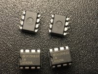
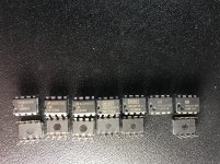
Being an amateur here - need some help if anyone can:
- Draw a diagram to illustrate how to set up this test
- Where to probe to test
- What are measurements for real/fake NE5532, LM4562?
Thanks!
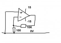
I think vacuphile means like this.
Iq should be within spec (similar to the values I measured) and the offset should be no higher than around 70 millivolts for the LM4562. The 5532 should be no higher than around 400mv. The offset is measured at the opamp output. Again, the offsets should be similar to my measurements I posted earlier.
Iq should be within spec (similar to the values I measured) and the offset should be no higher than around 70 millivolts for the LM4562. The 5532 should be no higher than around 400mv. The offset is measured at the opamp output. Again, the offsets should be similar to my measurements I posted earlier.
Attachments
Just to add that offset you measured for your 5532 was far to good for it to be a 5532 although the value of Iq was OK
Your first batch of LM4562 had far to high an offset to be genuine. Iq was a little low. These could be NE5532's
Your second batch had a very low Iq. Could be anything.
It will be interesting to see what the new test reveals.
Your first batch of LM4562 had far to high an offset to be genuine. Iq was a little low. These could be NE5532's
Your second batch had a very low Iq. Could be anything.
It will be interesting to see what the new test reveals.
My days of buying from disreputable dealers are well over.
I got a irfp9240 off ebay that lasted 10 minutes.
When I unplugged my soldering the mosfet blew up.
I got a replacement from RS Components and that has lasted days despite unplugging things trying to blow it up.
Got 3 flash drives from China and none worked.
Got some B9A pcb valve bases from Aliexpress and the valve wouldn't go into them it just bent the pins.
So had enough.....
Just to include here your earlier post for easy following:I think vacuphile means like this.
Iq should be within spec (similar to the values I measured) and the offset should be no higher than around 70 millivolts for the LM4562. The 5532 should be no higher than around 400mv. The offset is measured at the opamp output. Again, the offsets should be similar to my measurements I posted earlier.
NE5532: Iq = 7.50ma. Voffset = -450 mv
LM4562: Iq = 14.2ma. Voffset = + 27mv
My earlier post & now the DC offset measure for high gain 100:
Supply +- 15v (using voltage divider from 31.0v)
NE5532: (2 Op-amp in package)
Quiescent Current ~ 8 ma. (this is as per Iq in datasheet)
DC offset measured at Output ~ -10 & 20 millivolts (10K resistor between Output to -input, 100 resistor -input to 0v)
1st batch of LM4562: (2 Op-amp in package)
Quiescent Current ~ 8 ma
DC offset measured at Output ~ -4 & 28 millivolts (10K resistor between Output to -input, 100 resistor -input to 0v)
2nd batch of LM4562: (2 Op-amp in package)
Quiescent Current ~ 4 ma
DC offset measured at Output ~ 0.4 & 0.54 volts (10K resistor between Output to -input, 100 resistor -input to 0v)
I am going crazy from those chips:
1st Batch LM4562 (4 chip samples):
-1.097v~160mv
Quiescent Current ~ 8 ma
(test circuit with Op-amp=17.1ma , test circuit without Op-amp=9.2 => Op-amp=8ma)
2nd Batch LM4562 (4 chip samples):
120mv~700mv
Quiescent Current ~ 4 ma
(test circuit with Op-amp=13.1ma , test circuit without Op-amp=9.2 => Op-amp=4ma)
Maybe they are "Incredible Hulks" Op-amp
I don't understand the with and without opamp bit. I'm assuming you mean your resistive divider is drawing the constant 9ma ?
The wide range of offsets you quote for each batch is further 'proof' they are suspect. They should all fall within a narrow range.
Buy some samples from an authorised distributer and retest using those as a guide
The wide range of offsets you quote for each batch is further 'proof' they are suspect. They should all fall within a narrow range.
Buy some samples from an authorised distributer and retest using those as a guide
That different result was just came from using different method!Just to include here your earlier post for easy following:
My earlier post & now the DC offset measure for high gain 100:Code:NE5532: Iq = 7.50ma. Voffset = -450 mv LM4562: Iq = 14.2ma. Voffset = + 27mv
Supply +- 15v (using voltage divider from 31.0v)
NE5532: (2 Op-amp in package)
Quiescent Current ~ 8 ma. (this is as per Iq in datasheet)
DC offset measured at Output ~ -10 & 20 millivolts (10K resistor between Output to -input, 100 resistor -input to 0v)
1st batch of LM4562: (2 Op-amp in package)
Quiescent Current ~ 8 ma
DC offset measured at Output ~ -4 & 28 millivolts (10K resistor between Output to -input, 100 resistor -input to 0v)
2nd batch of LM4562: (2 Op-amp in package)
Quiescent Current ~ 4 ma
DC offset measured at Output ~ 0.4 & 0.54 volts (10K resistor between Output to -input, 100 resistor -input to 0v)
Code:The 5532 has to good an offset to be a 5532.
Your NE5532 is OK I assume. LTspice help me address this
.It just that Molly's method will give higher output DC offset.
I don't understand the with and without opamp bit. I'm assuming you mean your resistive divider is drawing the constant 9ma ?
The wide range of offsets you quote for each batch is further 'proof' they are suspect. They should all fall within a narrow range.
Buy some samples from an authorised distributer and retest using those as a guide
Your guess is correct!
- Status
- This old topic is closed. If you want to reopen this topic, contact a moderator using the "Report Post" button.
- Home
- Design & Build
- Parts
- Is this a fake LM4562NA?