I have an amplifier that uses two resistors to quieten the filament feed. The colour coding is something I've not seen before. The actual reading for the resistors is 50 Ohms but this not what the colour says, if it says anything. To me it appears to be grey-black-grey-gold. YMMV. I've attached a pic.
Thanks in advance for the help.
Thanks in advance for the help.
Attachments
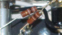
To me, it looks more like brown-black-brown-gold, but between your camera and my screen there are at least two layers of color spaces (and probably some more).
However, it could be consistent with your reading: if you measure the resistors after having removed all the tubes, this would leave them in parallel via the heater winding.
However, it could be consistent with your reading: if you measure the resistors after having removed all the tubes, this would leave them in parallel via the heater winding.
Agree with Elvee. Your resistors are connected together at one end in your photo. The other ends have the transformer winding in between them. It has a VERY low resistance, which essentially puts the resistors in parallel. So your two 100 ohm resistors in parallel measure about 50 ohms.
And it looks more like brown-black-brown-gold to me.
And it looks more like brown-black-brown-gold to me.
The 50 ohm reading I'm getting is for each resistor measured individually. They are actually configured as a potential divider with the joined leads connected to ground. As for the colour coding, it would have to be the lightest shade of brown I've ever come across. In real life it appears very washed out, almost pastel. If anything, it has more of a soft lilac tinge leaning more towards a grey or a silver than anything I'd call brown. Hence the  .
.
.Voltage divider?
You describe the classic pair of 100 ohm resistors wired from the two 6v winding wires of the heater supply to ground. SO yes, we can say it divides 6vAC into a pair of 3v with respect to ground. But step back and look at it. The combined ends of the 100 ohms are grounded, and the "free" ends go to either side of the 6vAC. Now unless you did something unusual, that 6v winding connects the free end of one resistor to the free end of the other. And the winding itself has a VERY low resistance. SO while you are looking at a 200 ohm series arrangement of resistors, you still have the less than an ohm resistance of the transformer winding from one end to the other. And that is pretty much the same thing as connecting those two free ends together. And that puts the resistors in parallel. That may nbot be the intent of the circuit, but it is still the case, and that is why on any amp with that virtual centertap circuit, the resistors will measure half the individual resistance. Half of 100 being 50.
You can measure each resistor separately, but unless you unwire them, you still have the rest of the circuit causing these readings.
Thanks to all that replied. They are indeed 100 ohm. I have had the same reply from an outside source, confirming what everyone has said. This third party was also able to add, knowing the resistor manufacturer, that this is their version of brown, even if one might not think of it as brown. I was failing to assess them in terms of the circuit as a whole and was focusing on an individual component.
Somedays my learning curve is more circular in nature.
Somedays my learning curve is more circular in nature.
- Status
- This old topic is closed. If you want to reopen this topic, contact a moderator using the "Report Post" button.