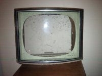
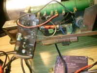
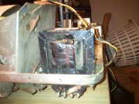
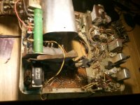
Hello. I have the guts of an old tv I pulled out of a skip. It had been robbed of all its tubes, mashed up and tossed aside. Shame cos it was a very beautiful ekco tv once. Anyway it is now dead so I would like to test the transformers to see if they are usable. There are four transformers in this thing, one is the output tran' of a single ended output stage, one is quite small and I have not looked at the circuitry around it to even begin to fathom its use. Another is in the power supply and I guess it is a 1:1 ?? But would this be rated for 240VAC, I guess so as the set is ac/dc, but I would just like some confirmation before a go throwing what is actually 272VAC in this area, at it. There is one last transformer of the same size, shape, number of windings and my guess is also a 1:1. could anyone that knows these old TV's let me know what I am playing with please. Thanks
You are playing with a live chassis TV. That means the mains is connected directly to the set and as it is AC/DC there is no mains transformer.
There will be an audio output transformer, a Line output transformer (tuned to either 405 line 10kHZ or 225 line 7kHZ approx) and a frame output transformer tuned to 25HZ,
There will be an audio output transformer, a Line output transformer (tuned to either 405 line 10kHZ or 225 line 7kHZ approx) and a frame output transformer tuned to 25HZ,
625 lines 15625Hz?JonSnell Electronic said:tuned to either 405 line 10kHZ or 225 line 7kHZ approx)
Frame OPT 50Hz but probably untuned.frame output transformer tuned to 25HZ,
A very old TV might have a mains transformer, but this might feed the valve heaters only. As Jon says, a model number will help.
Unfortunately the back was removed and I could not find it and I can not see a model number anywhere on it. I have no intention of plugging this thing in as I have no doubt that it is very dangerous even for those who do know these TV's. maybe if I look where the prim/sec are wired to someone may be able to have an educated guess of what one is what? I will try to give description of the remaining two unknown transformers and what they are wired to, tomorrow if one of you guys could help please? Thanks for replies I will update. For now, maybe this will give an idea of age....tv contained a u191 30p4 and possibly u26 (first letter is u second digit missing and third is a 6) but the cathode has a slightly different shape. The top of it is the same but going down toward the pins it looks like what I can only think to describe like, if you take a coke can and cut off the bottom and then cut 4 oblong sections out lengthways two large at opposite and two small opposite each other that is the shape of the cathode. Anyway those ones left inside as they was shielded by a half cylinder metal plate. Thanks for reading my waffle 
Last edited:
An AC/DC set never have a powertransformer, and the tube types point to serial heater chain. Some early sets had the HT to the picturetube, several kVolts, delivered from a mainstransformer, a big one but only in pure AC-sets.
One trafo is surely for the vertical deflection, one for audio out. One can possibly be a choke for the +B.
The description of the tubes electrode leads me to think that it is the anode you are talking of, a Beam Tetrode possibly. Does it have a top connection? Then it is the horizontal output tube (or valve for UK readers )
)
One trafo is surely for the vertical deflection, one for audio out. One can possibly be a choke for the +B.
The description of the tubes electrode leads me to think that it is the anode you are talking of, a Beam Tetrode possibly. Does it have a top connection? Then it is the horizontal output tube (or valve for UK readers
It is indeed a vacum tube thermionic valve  with the cathode conected to the top of the glass tube.(TRAF 1) One of the transformers is definately the output traf that does not appear to be air gapped but the center tap on the tube side is connected by cap resistor to one and other end of the windings, is this a usual arangement for a pp traf?. (TRAF 2) large transformer...... Has only a single winding and is connected one end to a really BIG cap (pysically size), and the other end of the winding is connected to a very tightly wound inductor of fine wire that is wound around a twig! with nails in it for teminals! (TRAFF 3)Is of same size core, but has two windings. (TRAF 4) Is the smallest, about the size one might expect in a 12 volt 500MA wall adaptor, i can see that at least one end of one winding is connected to pin one of an octal based 9 pin but that could surely mean anything?. This also has two windings. This set has two really big dropper resistors and i will try now to post some pictures but i do not know if thay will help at all. Thanks guys .... tuned or untuned to set frequency? what are the ramifications of running a tuned transformer at the wrong freq, and by "tuned" does it mean they are wound to a set tpv ratio for core size/frequency????
In a typical valve TV set there are only two transformers with some possible audio uses: the audio output transformer and the frame output transformer. Neither will be suitable for serious audio, as even the audio OPT will not have been designed for high quality. Think guitar practice amp, not hi-fi.
There will also be a line output transformer - completely useless for audio.
There will also be a line output transformer - completely useless for audio.
Woah! Did I read use a 240-250 volt primary with 272 volts? I would recommend having a Variac on hand & putting a ammeter on the transformers, & bring it up slowly to 272 volts. As the core saturates at a certain point the current will start to increase with an almost log curve. After about 110% rated input voltage the current starts to really climb. I would just get some form of 10 volt supply & see what you get out the other side first, THEN if you want to use them, find a way to regulate that 272 VAC back down to 240. There are some nice MOSFET designs out there on line, & half a dozen or more in books I have laying around. These regulate the primary mains side of the supply. ACDC radio & TV sets were notorious for being dangerous to service, but I am not in the UK. Over here in the States an isolation transformer was commonly used to drop the ground so you did not blow up the TV or your tools & test gear, including fingers. The old series filament arrangement attempted to get close to mains voltage across all the heaters, in some array of series a parallel arrangement, (usually they were purely series wired, especially in radios). In the 1930s this ACDC thing became very popular. It was one less transformer winding, if not no more Power Trans at all in a radio. They had 120-165 volt anode voltages on the tubes, (240 volts AC rectified in the UK wich worked way better with tubes than our crummy 110-117 volt unbalanced USA electrical system) . They used a "ballast tube" as a resistor, sometimes 2 ballast tubes. Whoop-deee-doo doo! These were essentially light bulbs that did not light up. (nothing but resistors in a glass bulb). It was all about cheaper manufacturing costs. Soon it became a big marketing sham too, as the ballast tubes were usually included in the tube count, in the advertisement. It made the radio seem much better than it really was. The Great Depression started the cheapening of radios to a point. WWII pushed it the rest of the way over the cliff. Just be careful my man! I started blackening outlets at the age of 5, & have not learned anything at all in the past 43+ years since. I have a little guitar amp (family heirloom thing, same model Jimmy Page used & all that rot) with the B+ terminals placed in the worst location imaginable. I tend to get a 400-450 volt jolt every time I need to go back in and fix anything. Sometimes pieces of my fingers stay behind smoking & sizzling between the B+ or OT primary & the ground terminals. The caps in it are great too! Even unplugged, I get nailed by it. It will be rebuilt, again, & should be good for another 10 years. So maybe find a 9-12 volt AC-AC adapter & use that & do some math. You can pry apart a cheap DC wall adapter, power supply (one that does not have wide range input a regulator in it) & remove the diodes inside it, & it becomes an AC to AC adapter. For some reason I can buy surplus 120AC to 9VDC wall warts much cheaper than the 120 VAC to 9 VAC ones. I routinely pull out the diodes & use them for digital audio signal processing unit power supplies. g. Somehow those power supplies command a "stupid price" & I can make a DC supply into an AC supply & glue it back together for about 1/3 the cost, including my labor. Lately I see more and more supplies that have a 16-48 volt in 12 volt out regulator, so they can just change the plugs & sell the things anywhere in the world. The old style with a transformer diodes, resistors & capacitors only is what you want. Rip out that junk, & hook up to the transformer & see what comes out. It should be AC voltage.
Woah! Did I read use a 240-250 volt primary with 272 volts? I would recommend having a Variac on hand & putting a ammeter on the transformers, & bring it up slowly to 272 volts. As the core saturates at a certain point the current will start to increase with an almost log curve. After about 110% rated input voltage the current starts to really climb. I would just get some form of 10 volt supply & see what you get out the other side first, THEN if you want to use them, find a way to regulate that 272 VAC back down to 240. There are some nice MOSFET designs out there on line, & half a dozen or more in books I have laying around. These regulate the primary mains side of the supply. ACDC radio & TV sets were notorious for being dangerous to service, but I am not in the UK. Over here in the States an isolation transformer was commonly used to drop the ground so you did not blow up the TV or your tools & test gear, including fingers. The old series filament arrangement attempted to get close to mains voltage across all the heaters, in some array of series a parallel arrangement, (usually they were purely series wired, especially in radios). In the 1930s this ACDC thing became very popular. It was one less transformer winding, if not no more Power Trans at all in a radio. They had 120-165 volt anode voltages on the tubes, (240 volts AC rectified in the UK wich worked way better with tubes than our crummy 110-117 volt unbalanced USA electrical system) . They used a "ballast tube" as a resistor, sometimes 2 ballast tubes. Whoop-deee-doo doo! These were essentially light bulbs that did not light up. (nothing but resistors in a glass bulb). It was all about cheaper manufacturing costs. Soon it became a big marketing sham too, as the ballast tubes were usually included in the tube count, in the advertisement. It made the radio seem much better than it really was. The Great Depression started the cheapening of radios to a point. WWII pushed it the rest of the way over the cliff. Just be careful my man! I started blackening outlets at the age of 5, & have not learned anything at all in the past 43+ years since. I have a little guitar amp (family heirloom thing, same model Jimmy Page used & all that rot) with the B+ terminals placed in the worst location imaginable. I tend to get a 400-450 volt jolt every time I need to go back in and fix anything. Sometimes pieces of my fingers stay behind smoking & sizzling between the B+ or OT primary & the ground terminals. The caps in it are great too! Even unplugged, I get nailed by it. It will be rebuilt, again, & should be good for another 10 years. So maybe find a 9-12 volt AC-AC adapter & use that & do some math. You can pry apart a cheap DC wall adapter, power supply (one that does not have wide range input a regulator in it) & remove the diodes inside it, & it becomes an AC to AC adapter. For some reason I can buy surplus 120AC to 9VDC wall warts much cheaper than the 120 VAC to 9 VAC ones. I routinely pull out the diodes & use them for digital audio signal processing unit power supplies. g. Somehow those power supplies command a "stupid price" & I can make a DC supply into an AC supply & glue it back together for about 1/3 the cost, including my labor. Lately I see more and more supplies that have a 16-48 volt in 12 volt out regulator, so they can just change the plugs & sell the things anywhere in the world. The old style with a transformer diodes, resistors & capacitors only is what you want. Rip out that junk, & hook up to the transformer & see what comes out. It should be AC voltage.
Just to clarify, the 240V system over here isn't what you would call balanced. The supply is 240V live (hot) to neutral. Neutral is still the 0V reference and tied to earth just like yours. Most houses just have a single live and a neutral.
However most cities and suburbs (here in Australia anyway) get fed a 240/415V 3 phase supply and a neutral to the street from a local 11kV 3 phase transformer and every 3rd house shares a phase. (Except for commercial properties and residences that have requested 3 phase service like mine)
Out in rural areas we have what's called SWER, which is just a single 11kV phase with earth return, and the transformers are a centre tapped neutral design much like your residential supply transformers, giving you 240-0-240 or 480 between both ends of the transformer.
- Home
- Design & Build
- Parts
- Old ekco tv transformers


