Hi chaps,
I have two fairly straightforward questions for you passive component experts, or anyone really")
Background
I have a rather modified CD63ki, and yesterday I went searching for more guidance on modifying it, after mostly exhausting Thorstens tweaks on TNT-audio TNT-Audio, and reclocking.
Looking on Audioasylum I quickly realised the name Bobwire was synonymous with CDP tweaking. Eventually I found what I was looking for: Bobwire's article/post. This is an excellent guide, and obviously some of it overlaps with Thorstens mods, but from it I have a couple of questions:
Questions I have
1 - It is suggested to use a tantalum capacitor in one place:
"CAPACITOR ON THE RF AMP PCB:
C106 REPLACED BY DIPPED TANTALUM CAP."
Why use a tantalum, I've often read they are crap for audio? Would it be sensible to use a ~.5uf film cap or a good electrolytic instead? Or is tantalum just well-suited to this application? If so, what size is appropriate - 1uf, 10uf??
2 - He says to use 16v/1000uf caps all over the place, which seems nice. Can someone suggest a suitable reasonable quality cap, which is available in the UK? I wanted to use Nichocon MUSE FS, as they are meant to be good, and the price is bearable. However, they are about 1.2cm diameter, which seems too large for many places. Something 1cm d. would be better...
Would Rubycon ZL be appropriate/decent? These are well-priced, a good size, and have these 'features':
"--40% Lower impedance than conventional low impedance electrolytics
--High ripple and low impedance offers component reduction or miniaturisation opportunities"
These caps are mainly to go around the chips, opamps, and hdam buffer.
Any advice appreciated, thanks! (sorry for the longish post, I'm crap at brevity)
ps--anyone replace traces with coax, as seems popular? It looks like a nightmare task...
I have two fairly straightforward questions for you passive component experts, or anyone really
Background
I have a rather modified CD63ki, and yesterday I went searching for more guidance on modifying it, after mostly exhausting Thorstens tweaks on TNT-audio TNT-Audio, and reclocking.
Looking on Audioasylum I quickly realised the name Bobwire was synonymous with CDP tweaking. Eventually I found what I was looking for: Bobwire's article/post. This is an excellent guide, and obviously some of it overlaps with Thorstens mods, but from it I have a couple of questions:
Questions I have
1 - It is suggested to use a tantalum capacitor in one place:
"CAPACITOR ON THE RF AMP PCB:
C106 REPLACED BY DIPPED TANTALUM CAP."
Why use a tantalum, I've often read they are crap for audio? Would it be sensible to use a ~.5uf film cap or a good electrolytic instead? Or is tantalum just well-suited to this application? If so, what size is appropriate - 1uf, 10uf??
2 - He says to use 16v/1000uf caps all over the place, which seems nice. Can someone suggest a suitable reasonable quality cap, which is available in the UK? I wanted to use Nichocon MUSE FS, as they are meant to be good, and the price is bearable. However, they are about 1.2cm diameter, which seems too large for many places. Something 1cm d. would be better...
Would Rubycon ZL be appropriate/decent? These are well-priced, a good size, and have these 'features':
"--40% Lower impedance than conventional low impedance electrolytics
--High ripple and low impedance offers component reduction or miniaturisation opportunities"
These caps are mainly to go around the chips, opamps, and hdam buffer.
Any advice appreciated, thanks! (sorry for the longish post, I'm crap at brevity)
ps--anyone replace traces with coax, as seems popular? It looks like a nightmare task...
Hmmm, don't know that I can help, I'm just getting together a list of replacement caps, was using all Panasonic FC series, but found that don't have a 47uf.
I just found rubycon ZA series, which is even lower impeadance than the ZL at 60% lower than normal low impeadance, although the suggested application is high speed digital and SMPS.
Don't know whether it makes any difference for audio......
Tony.
I just found rubycon ZA series, which is even lower impeadance than the ZL at 60% lower than normal low impeadance, although the suggested application is high speed digital and SMPS.
Don't know whether it makes any difference for audio......
Tony.
hi wintermute,
Thanks for the reply, I was beginning to think noone would say anything!
I've often heard Panasonic FC caps are good sounding and cheap. I can get those, so I think plenty of 1200uf 16v are in order. I'm thinking of using WIMA 0.1uf metalised polyester to bypass them with.
Would it sound extra good to bypass critical ones with an additional film and foil 0.01uf polypropylene WIMA? I'm crap at soldering, and 3 caps together is obviously tough work, but if it will give an excellent result...
Another spot can probably take a 16v/3300uf (C806). Crap thing is, next to this (C805) Bobwire recommends a 35v/4700uf!!! Now, what kind of cap will fit into a 1cm diameter space, and is anything more than 1000uf?!?!?
BTW, Wintermute - do you have the same/similar player? If so, what else have you done to improve it?
Hi SimontY
I'm probably as much a newbie on caps as you are... I chose Panasonic FC's because they are readily available and quite a few people here seem to like them, thought it would be a safe bet. I'm ordering new ones for my 16 year old amp, which is starting to develop some problems. I think you are on the right track with the bypassing idea, from what I've read seems to be the way to go. Are you going to solder them on the reverse side of the board?
I did a search on Rubicon caps and a few people mentioned the ZA's and seemed to like them. The other interesting thing mentioned was that Rubycon make the black gate caps.
I'm going out on a limb and replacing my bypass caps (as well as a couple of greencaps which I'm not sure of the function of) in my amp with Revox Rifa, Metallised Polyphenylene Sulphide (PPS) caps (currently they are all greencaps). Couldn't find much info on them (other than spec sheets which look good, to my inexperienced eyes) but thought I'd give it a go. I don't know that I'm going to be qualified to say whether they make a difference or not
I just replaced all the ceramics with NPO ceramics, and I can't honestly say whether it made a difference, too much time between when I disconnected everything, and hooked it back up! (My speakers probably aren't detailed enough to pick up subtle amp differences anyway). It's the electros, though that I'm hoping will make a difference (if for no other reason than their age). Have yet to run an rmaa test on it to see if there is any measurable difference, in distortion.
I've got a Marantz DV18 MK II, haven't touched it..... Only just out of warranty about a month ago. I think I have more severe probs with my amp and speakers, so have been trying to concentrate on them, but I guess eventually I'll get to the DV18
Have you got a decent soldering iron or soldering station? I had a cheap 25W iron for years, and eventually splurged and bought a Hakko 936 soldering station. Man did that make a difference! Highly recommend a good rig!!! The adjustable temperature is great, it's really useful when soldering "Heavy" stuff that normal soldering irons simply cool down on. You can do it quickly without overheating anything. I've only got the standard tip, but the difference is like chalk and cheese.
Tony.
I'm probably as much a newbie on caps as you are
... I chose Panasonic FC's because they are readily available and quite a few people here seem to like them, thought it would be a safe bet. I'm ordering new ones for my 16 year old amp, which is starting to develop some problems. I think you are on the right track with the bypassing idea, from what I've read seems to be the way to go. Are you going to solder them on the reverse side of the board? I did a search on Rubicon caps and a few people mentioned the ZA's and seemed to like them. The other interesting thing mentioned was that Rubycon make the black gate caps.
I'm going out on a limb and replacing my bypass caps (as well as a couple of greencaps which I'm not sure of the function of) in my amp with Revox Rifa, Metallised Polyphenylene Sulphide (PPS) caps (currently they are all greencaps). Couldn't find much info on them (other than spec sheets which look good, to my inexperienced eyes) but thought I'd give it a go. I don't know that I'm going to be qualified to say whether they make a difference or not
I just replaced all the ceramics with NPO ceramics, and I can't honestly say whether it made a difference, too much time between when I disconnected everything, and hooked it back up! (My speakers probably aren't detailed enough to pick up subtle amp differences anyway). It's the electros, though that I'm hoping will make a difference (if for no other reason than their age). Have yet to run an rmaa test on it to see if there is any measurable difference, in distortion.
I've got a Marantz DV18 MK II, haven't touched it..... Only just out of warranty about a month ago. I think I have more severe probs with my amp and speakers, so have been trying to concentrate on them, but I guess eventually I'll get to the DV18
Have you got a decent soldering iron or soldering station? I had a cheap 25W iron for years, and eventually splurged and bought a Hakko 936 soldering station. Man did that make a difference! Highly recommend a good rig!!! The adjustable temperature is great, it's really useful when soldering "Heavy" stuff that normal soldering irons simply cool down on. You can do it quickly without overheating anything. I've only got the standard tip, but the difference is like chalk and cheese.
Tony.
My bypass caps will be going on the reverse side yes. I've got quite a few there already from previous changes, and things have only ever got better...Bits originally posted by wintermute
...I think you are on the right track with the bypassing idea, from what I've read seems to be the way to go. Are you going to solder them on the reverse side of the board?...
...The other interesting thing mentioned was that Rubycon make the black gate caps...
...I just replaced all the ceramics with NPO ceramics, and I can't honestly say whether it made a difference...
...I've got a Marantz DV18 MK II, haven't touched it...
...Have you got a decent soldering iron or soldering station?
Tony.
I noticed that Rubycon make BG, and that sort of piqued my interest
But the Panasonic ones are 'miniature' so I'm gonna get those I think.What are NPO ceramics? Actually, I just searched(!) and they are 'more stable'. So I guess they're just superior types.
Just did a search for your DV18, looks like a good player. But I bet it could be better
Actually, I haven't got a good soldering iron, mine is a diabolical cheap piece of crap, with a tip that bends and bluntens just from being left on! I have pulled out solder-tags and had solder running to the wrong places, and all sorts of nightmares, when using this iron. My problem with getting a good one is partly not knowing what exactly I need, and the fact that soldering stations cost a lot of money
Any advice in this area would be appreciated, because I will have more difficult jobs in the future. For example, changing my op-amps was a pretty tough task for me! Couldn't do anything more fiddly than that...

Cheers
Hi SimontY,
Yeah from what I can gather normal ceramics tend to be a source of distortion, but NPO types are apparently superior, in that respect, as well as in temperature related performance.
I think changing op-amps (especially if they are bigger than 8 pins) is a challenge for anyone, unless you have some serious desoldering gear! I use desolder braid, but it is slow and a bit hit and miss.
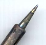
I only have the one tip for my iron, pic attached. I find this type of tip good for general soldering, although I could probably do with a chisle point tip for heavy duty soldering (such as power supply wiring). Note that my tip looks worse than it is, because I didn't clean it after use the last time.
If you don't want to fork out for a soldering station I would suggest getting a reasonably high power (say 50W) iron with a variable temperature control (this bit is important especially with a high wattage iron, or when soldering stuff like op-amps). Get one with a choice of tips available not the screw in type but the slot in ones with a sheath that tightens down over them.
I did have an iron like I just described for a while before the hakko (after the two or three cheap and nasty ones) but when it blew up I bought the hakko, and it really is a major improvement over even the decent iron I had before it.
here are some user reviews of my Iron. They are certainly cheaper overseas than here in Aus. I paid $200Aus for mine!
http://www.eham.net/reviews/detail/2871
Tony.
Yeah from what I can gather normal ceramics tend to be a source of distortion, but NPO types are apparently superior, in that respect, as well as in temperature related performance.
I think changing op-amps (especially if they are bigger than 8 pins) is a challenge for anyone, unless you have some serious desoldering gear! I use desolder braid, but it is slow and a bit hit and miss.
I only have the one tip for my iron, pic attached. I find this type of tip good for general soldering, although I could probably do with a chisle point tip for heavy duty soldering (such as power supply wiring). Note that my tip looks worse than it is, because I didn't clean it after use the last time.
If you don't want to fork out for a soldering station I would suggest getting a reasonably high power (say 50W) iron with a variable temperature control (this bit is important especially with a high wattage iron, or when soldering stuff like op-amps). Get one with a choice of tips available not the screw in type but the slot in ones with a sheath that tightens down over them.
I did have an iron like I just described for a while before the hakko (after the two or three cheap and nasty ones) but when it blew up I bought the hakko, and it really is a major improvement over even the decent iron I had before it.
here are some user reviews of my Iron. They are certainly cheaper overseas than here in Aus. I paid $200Aus for mine!
http://www.eham.net/reviews/detail/2871
Tony.
Attachments
Thanks for the advice wintermute!
I need to search around for a good value station. The only place I've properly looked is Farnell, they have loads, but the cheapest is about £70, which is quite a lot for me. Thats 165 of your magic Aussie beans
You've got me convinced that its something I need though now, because I have much more soldering to do on my CDP, and I want to build a gainclone soon. I also want to put fancy diodes in my current amp, which I can't afford to break!
Thanks
Yeah when you look at how much we spend on components (whether individual parts or a DVD player etc), the cost of a good soldering station starts to look pretty cheap Especially when you consider how long a good one should last, and how much benefit you should get from it.
It always amazes me how much easier things get when I get the right tool for the job, I always think, why didn't I do that sooner!
Tony.
Especially when you consider how long a good one should last, and how much benefit you should get from it.It always amazes me how much easier things get when I get the right tool for the job, I always think, why didn't I do that sooner!
Tony.
Not really good guide and certainly can be misleading for beginners. A few "tweaks" suggested in this article can screw up the sound nicely. Some are good though.SimontY said:Looking on Audioasylum I quickly realised the name Bobwire was synonymous with CDP tweaking. Eventually I found what I was looking for: Bobwire's article/post. This is an excellent guide, and obviously some of it overlaps with Thorstens mods (...)
Zombie said:I recommend matching the 10k and 27k resistors at the diff.amps after the DAC within 0,1% or better. Makes a great difference in sound quality...
The difference is certainly not great if exists at all.
Pedja
Not really good guide and certainly can be misleading for beginners. A few "tweaks" suggested in this article can screw up the sound nicely. Some are good though.
Well, since you have an opinion, wouldn't it be nice to know - according to you - what Bobwire mods are not good and which are and why, if applicable?
The difference is certainly not great if exists at all.
and you base that on...?
Cheers,
tom
Of course. His supply decoupling methods are 50 years old and are not applicable for the digital circuits. He could be also more careful with “swap the resistor with choke or jumper it” approach since if you do what he recommends for R107 you will alter the operating points in the RF amp and the result will be the fatiguing sound (yes, I did tried it). Let me stay deeply convinced that there is not an important misunderstanding behind the mentioning of the I/V opamps in CD63. At the other hand, the signal lines shielding suggested by him yields good results. For more I should dig a bit, it was long time ago that I bothered with this.Zombie said:Well, since you have an opinion, wouldn't it be nice to know - according to you - what Bobwire mods are not good and which are and why, if applicable?
Sorry? If you meant to ask did I try, the answer is yes, I did.
and you base that on...?
Pedja
OK, then we are of differing opinions conc the matching and its results...
Anyway, would be nice to have your opinion about the bulk of the Bobwire mods, as it will cost a lot (buying caps) or involve operations that can't be reversed so easily (the coax stuff).
I have thought about the coax replacements a long time, but haven't got around to it. Do you mean that only the digital signal to the DAC is worthwhile or ALL the coax mods?
Have you done any shielding of the different chips onboard? What results?
What are the "Top 5" mods in your opinion (once the output caps are changed or shorted)?
Cheers,
tom
Re: Talking about Bobwire
Hi,
The change was enormous, if not entirely for the better in the context of the entire system. The sound became more refined and softer, I think with better imaging, but it sounded dull.... until I fixed more problems. (I should add that I also broke my display at the same time, which perhaps contributed to the sonic change.) I used 1% metal film, and changed nearly all around the DAC and output stage.
My favorite mods were:
(obviously removing those caps!!)
1 damping with bitumen and using oak cones (by far biggest musicality upgrade!!!)
2 changing some diodes to shottky, and using a cap on the mains input (less harsh, sweeter treble, better all-round)
3 changing op-amps to OPA2604, decoupled with 220nf (bolder sound)
4 feeding my new clock with external home made 5v psu (timing and solidity, and everything!)
5 reclocking with Audiocom clock
I've probably got the order a bit off or forgotten something good, but there you go. Besides, those top 5 wouldnt make a virgin player sound like mine - there are a number of other little things that were nice done too
Hmm, not got round to replacing R107 yet! I think I'll leave it alone now
I've replaced quite a few power line resistors with inductors and ferrite beads - the noise floor is amazing, I can hear all sorts of little details that I had no clue were there. All manner of hiss and crap on CDs! And I still have no clue about these subleties hearing something like an Arcam FMJ or Linn Genki, admittedly in a hi-fi shop...
Hi,
Thanks, I did this the last time you recommended itZombie said:I recommend matching the 10k and 27k resistors at the diff.amps after the DAC within 0,1% or better.
The change was enormous, if not entirely for the better in the context of the entire system. The sound became more refined and softer, I think with better imaging, but it sounded dull.... until I fixed more problems. (I should add that I also broke my display at the same time, which perhaps contributed to the sonic change.) I used 1% metal film, and changed nearly all around the DAC and output stage.
I guess you wanted him to answer this, but I shielded the chips, it didn't change the sound very much, seemed to lose some harshness and become more refined.Zombie said:
Have you done any shielding of the different chips onboard? What results?
What are the "Top 5" mods in your opinion (once the output caps are changed or shorted)?
My favorite mods were:
(obviously removing those caps!!)
1 damping with bitumen and using oak cones (by far biggest musicality upgrade!!!)
2 changing some diodes to shottky, and using a cap on the mains input (less harsh, sweeter treble, better all-round)
3 changing op-amps to OPA2604, decoupled with 220nf (bolder sound)
4 feeding my new clock with external home made 5v psu (timing and solidity, and everything!)
5 reclocking with Audiocom clock
I've probably got the order a bit off or forgotten something good, but there you go. Besides, those top 5 wouldnt make a virgin player sound like mine - there are a number of other little things that were nice done too
Hmm, not got round to replacing R107 yet! I think I'll leave it alone now
I've replaced quite a few power line resistors with inductors and ferrite beads - the noise floor is amazing, I can hear all sorts of little details that I had no clue were there. All manner of hiss and crap on CDs! And I still have no clue about these subleties hearing something like an Arcam FMJ or Linn Genki, admittedly in a hi-fi shop...
Pedja,
I appreciate you warning us about potential downgrades to sound quality. I am a beginner essentially.
Would you please elaborate on what is hot and what is not?
For example, I intend to solder in a fair load of Panasonic FC 1,200uf caps as he suggests. Good or bad idea?
Hmm, here's a tough question:
How the hell do you do the coax swaps to the transport and still have the ability to remove the main pcb for further work???
(I can barely imagine this player having better sound, but there is still a slight harshness and hardness, hmm, coax......)
Zombie said:I have thought about the coax replacements a long time, but haven't got around to it. Do you mean that only the digital signal to the DAC is worthwhile or ALL the coax mods?
At the moment I did it only with the eye-pattern. Later I was forced to replace some other leads (those sockets are not the world-class and after you retrieve the ribbon cable a few times…) and put new cables which were not shielded but still were shorter. I am not sure if I could hear the difference then.
Have you done any shielding of the different chips onboard? What results?
Shield the uP to hear if you like the shielding or not. (I do.) A few square cm of copper and a drop of glue is all you need.
What are the "Top 5" mods in your opinion (once the output caps are changed or shorted)?
Not really Top Five but I wrote here something like that:
http://users.verat.net/~pedjarogic/audio/cd_mods/cd_mods.htm
If I’d start again with this player, I’d probably go opampsless (applies to the HDAMs too) in the analog stage.
SimontY said:For example, I intend to solder in a fair load of Panasonic FC 1,200uf caps as he suggests. Good or bad idea?
Bad.
Hmm, here's a tough question:
How the hell do you do the coax swaps to the transport and still have the ability to remove the main pcb for further work???
Pull out the R501 and solder eye-pattern cable there and you'll have it available for desoldering before you remove the board. If you replace majority or all leads… well, announce the end of the works.
(I can barely imagine this player having better sound, but there is still a slight harshness and hardness, hmm, coax......)
As said above, I would probably do some things different now, but even then, my guess is this player ultimately can not sound as clean, quiet and natural as non-o/s can do. But this is not pooh-pooh about it, I think it is pretty good player which, tweaked, can be as good as delta/sigma unit can be. Even if I would start to build delta/sigma DAC from the scratch, there are no many equal or better chips than SM5872. Maybe some current output ones… will try once.
Pedja
Thanks Pedj,
Don't really understand: "Pull out the R501 and solder eye-pattern cable there and you'll have it available for desoldering before you remove the board."
Please quickly say why putting in better caps is bad. Are they too low quality to really help, or just too big? What performance parameter determines "bad" here? ESR?
Should the main smoothing caps be big fellas?
Cheers
Hi SimontY,
Pedja
R501 is the place where the HF (eye-pattern) signal is coming to the main board. Pull out of the board one end of that resistor and solder the cable there - you could later desolder the cable before you pull out the board.SimontY said:Don't really understand: "Pull out the R501 and solder eye-pattern cable there and you'll have it available for desoldering before you remove the board."
It is good to put better caps but it is not good to put bigger caps. Actually if you look the ESR at 100Hz, bigger caps are better. It is their inevitable higher inductance (= higher impedance at higher freqs) that makes them not wanted in the digital circuits. O yes, if I'd go again with this player, I'd also put a few regulators more in it. Decoupling wize.Please quickly say why putting in better caps is bad. Are they too low quality to really help, or just too big? What performance parameter determines "bad" here? ESR?
IMO those caps before the regs for the analog part should be bigger.Should the main smoothing caps be big fellas?
Pedja
SimontY said:hi wintermute,
Another spot can probably take a 16v/3300uf (C806). Crap thing is, next to this (C805) Bobwire recommends a 35v/4700uf!!! Now, what kind of cap will fit into a 1cm diameter space, and is anything more than 1000uf?!?!?
Does the CD67 have more room? I had lots of room for four Nichicon 4700uF/35v FX Muse caps in place of C803, C804, C805, and C806.
Regards,
Dan
- Status
- This old topic is closed. If you want to reopen this topic, contact a moderator using the "Report Post" button.
- Home
- Design & Build
- Parts
- 2 questions re. caps for use in Marantz CD63