Hi There
I have a double sided pcb, and I want to get a schematic from it, someone here has idea about this? for example the best way to do this, software who is capable of generate connections from a pcb drawn in the pcb section wil sure help.
thanks for the help.
regards
kees
I have a double sided pcb, and I want to get a schematic from it, someone here has idea about this? for example the best way to do this, software who is capable of generate connections from a pcb drawn in the pcb section wil sure help.
thanks for the help.
regards
kees
Do you have photoshop (or other such program?) Scan or photograph both sides. You can use the tools to render the contrast different, allowing you to see the margins of the traces. Then use the free-form drawing tool to go over the top side traces in green, the bottom side traces in green. "Flop" the bottom image and merge. Once you have this "x-ray" drawing you can print it out and label the nodes by hand, and connect in Tina, Multisim or LTSpice.
Is the PCB damaged?
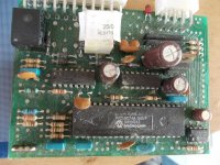
There is a programmable micro on there so you will need the code, unless you are just replacing the board. The PIC micro is also not readily available anymore.
Are device codes visible for the 16 pin devices?
Have fun, I think you may find it quite a job, also get a multimeter that will make a noise when there is a short, as you will have to check the connections.
The PIC micro is also not readily available anymore.
Are device codes visible for the 16 pin devices?
PIC 16C74A IS available, although you'd probably use a 16F74
The pic is a PIC16C74A-041/P and is available here. The board is a LPG gas stepmotor driver, it uses a oxigen measurement
and decide then how much LPG the car engine needs, this way I have always the optimal LPG /oxigen mix.
It is for old cars. I have also a digital ignition with a digital advancer who is adjustable with a lcd panel and afterward it can removed.
this uses a risc processor because here we need speed.
regards
Last edited:
PIC 16C74A IS available, although you'd probably use a 16F74
I either typed in a code wrong, only got newer quad packages, just typed the above in, they are still out there in DIP package.
Reverse engineering a PCB (especially if you cant depopulate it) is as stated previously get the data sheets.
Sort the power connections first.
Pick a master IC, the pic in this case and create a netlist for each pin using a method of visual and and multimeter.
Transfer to schematic, easier for initial stages to draw device symbol as actual chip pin outs (instead of functional block diagram).
Check, check and check again, much easier than the PCB being wrong.
Hi Marce
I do now it is tricky, but this pcb is not that complicated, maybe the photoshop way is the best to see where it al go.
Two ic are also clean sweeped, so I do not now what it is, I think a analog ic.
I go to a friend with a special visual scope to see what it is.
it will work, the factory give not schematics of it and possible some code is write protected.
Hi Kees52, the photoshop way is Ok if you have a blank board, even then you still need to check out the connectivity, I work in a PCB design bureau an we do this occasionally and getting it right is paramount, and more painful than people expect even for a simple board.
Yes it was common practice to grind of the code of an IC to make it harder to reverse engineer. When you get a schematic done sometimes you can get the functionality from the pin outs (op-amps, 4000 and 74 series logic having well defined output patterns) some other ICs especially if a bit esoteric can be harder to work out.
Yes it was common practice to grind of the code of an IC to make it harder to reverse engineer. When you get a schematic done sometimes you can get the functionality from the pin outs (op-amps, 4000 and 74 series logic having well defined output patterns) some other ICs especially if a bit esoteric can be harder to work out.
Hi Marce
I can afcourse put the components of, but it is though hole double sided with a lot of via,s.
So it will take time.
I have a friend who has company who make pcb and stuck them , he have good solder equipment for this, so I do first put the components in ultiboard as seen on the pcb itselfs then remove all components.
I would recommend if this is your only working board not to try an remove them all, it may cause more problems than it solves.
We had to copy a board from a Nuclear power plant, all populated, 74 series ICs and processors 8 layers! Took the guy who ended up doing it 3 months...
Yours wont take that long though...
We had to copy a board from a Nuclear power plant, all populated, 74 series ICs and processors 8 layers! Took the guy who ended up doing it 3 months...
Yours wont take that long though...
Hoy marce
I think it is not so much work, I have inspected it and all traces I can find, also the more I do the more clearly it get, circuit is not so extreme difficult, it is just a LPG injector driver who look at the oxigen sensor to deside how much keep it to 1 or less , I can change this with software, older engines don't may so lean because of heat.
If I put the board on a light I can see clearly through the board.
- Status
- This old topic is closed. If you want to reopen this topic, contact a moderator using the "Report Post" button.
- Home
- Design & Build
- Parts
- Make schematic from pcb