Hello everyone this is my first post on this forum but I have been coming here for a few months now. I have a couple things I was hoping someone could help me out with? I tore apart an old Philips stereo found on the side of the road,I thought maybe there would be something in it I could use. It was a 5.1 "surround" stereo w/ powered subwoofer,yes I got the sub and opedned it up too. Anyways,there were a few things I thought may be of some use,first off in the subwoofer there was a medium sized transformer and I plugged it in an powered it up and it read 20.2-0-20.2volts. There was also a mono chip amp that used a TDA7296 chip. It does work but of course it is setup for lower freqs. Now in the actual stereo there was a huge transformer but Im not sure how to even hook it up and what is the input/outputs. It says Billion on it along with some numbers/letters I searched the numbers/letters and name and could not find the exact power supply. I did take some pics and was hoping maybe someone could tell me how to hook it up and then I can just get the readings from my multimeter,or if you know the model and specs and could send me a link to it that would be great too! Before I post the pics there were some bigger amp chips for the actual stereo one reads STK496-070C,that one has the main front L/R speakers on the board and the other big chip reads STK407-070 that board has the surround L/R and center speakers on it. I tried searching each chip and I could not find anything except That they are Sanyo amplifier chips. (I think thats what it said?) My main concern is finding out what voltage this huge transformer is and if it even works and how to hook it up to find out! But any info on anything else I have listed would be great too! Is any of this stuff worth keeping? Sorry for the long first post and thanks in advance for any help. Pics coming up.....
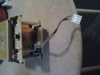
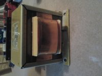
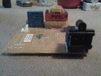
Dont know what happen with the pics let me try again. I am trying to upload pics of the big transformer I found and need specs/info on it and which wires are what. The last pic is the board that the transformer plugged in to and then that board plugged in to the wall.
Attachments
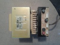
You have got the currant ratings for the secondaries there as the fuses are still present.
Those STK chips fail at the drop of a hat and are not very much more than a couple of complimentary pairs inside if you can get an internal circuit for them. I have seen a manual for an amp with them in it that showed them as about 6 transistors in a box.
Those STK chips fail at the drop of a hat and are not very much more than a couple of complimentary pairs inside if you can get an internal circuit for them. I have seen a manual for an amp with them in it that showed them as about 6 transistors in a box.
Thanks for the responses! I tried connecting the trans. to the board and then plugged in to the wall but I couldnt get any voltage readings on any of the wires coming out of the transformer but then again Im not sure what wires are what. Well there are not really even wires coming directly out of it except the 2 brown ones which I assume are the Vinput? I got another transformer out of the case too,it is about 3 times smaller and it has 2 wires (red/white) on one side which is the Viput and then 3 wires (blue/orange/blue) which I found orange to be ground and the 2 blues +20.2. I am not sure on the amperage output of the smaller transformer,how can I find that out? Anyways thanks for the replies,I dont really care about the chips I mainly just wanted the transformers out of it but its bugging me not knowing what size/Vout the bigger one is. Im assuming since it is almost 3x bigger than the 20.2-0-20.2 trans that it is a higher output V and probably higher Amp too. As for the fuses on the little board connected to the trans.there are 4 total (3black,1red) the 2 black ones furthest to the right say T5A 250V and the red and black one on the left side say black:T2 5A 250V red:T1,6A 250V.
You will need to follow the tracks from the ghetto blaster mains socket to the socket the plug with the brown leads goes to.
There is most likely a location where a power switch was once connected. You will need to bridge the connections to it to get power to the transformer.
The fuses give a good clue to the currant ratings and a volt meter will do it for the voltages.
There is most likely a location where a power switch was once connected. You will need to bridge the connections to it to get power to the transformer.
The fuses give a good clue to the currant ratings and a volt meter will do it for the voltages.
Thanks for the help guys. I will try what you all have suggested. I think the smaller transformer will work fine for my upcoming project thugh. It reads 20-0-20V but Im not sure on the amperage. Is there a way I can find that out with the multimeter? I am thinking about trying a LM1875 chip amp,one of the kits you have to solder yourself from Ebay. The recommended power for the board Im looking at is AC 19-0-19,will the 20-0-20 transformer I have be OK? Actually it reads more like 20.2(.3)-0-20.2/(.3) or so. Should I just start a new thread about the LM1875? b/c Im sure Ill have a lot more questions.
Well I figured it out and was able to get some readings on the multi-meter. Someone here suggeted that the board the trans. was connected to was hooked up to a switch,it was and I guess since the switch was not still connected the board was just "off". So I just connected the transformer directly to the wall using the 2 brown input wires and an old power cord. Now this transformer had 3 sets of outputs that were connected by a socket,I guess thats what you can call it,each one was fused also. So the first output was a set of 3 wires and they read 10v-0-10v,just your normal split type output,next was 4 wires now I could not figure out what the first 2 wires in the group of 4 did,they were not grounds and they didnt read a voltage so Im clueless as to what purpose they served and I tried every combination I could with my multi-meter but the 3rd wire was 5volts and the 4th was the ground. Next was the group of 5 wires. The first was 56volts,2nd 56volts,3rd 28Volts,4th GND,5th GND.
After figuring everything out,I will probably not be using this transformer unless I need a ton of volts for a high power sub amp or something down the road but thats just too much for me right now. Plus I have a smaller more simple transformer that I will probably be using for my upcoming chip amp. It is just 20v-gnd-20v so that will work out great for what I will be using it for. I do have one more question though, with a transformer that is v-0-v like the smaller 20-0-20 I have,can I just use one of the V and the gnd? So instead of 20-0-20 could I just use 20-0 and leave the other 20V un-used? Thanks again for the replies!
After figuring everything out,I will probably not be using this transformer unless I need a ton of volts for a high power sub amp or something down the road but thats just too much for me right now. Plus I have a smaller more simple transformer that I will probably be using for my upcoming chip amp. It is just 20v-gnd-20v so that will work out great for what I will be using it for. I do have one more question though, with a transformer that is v-0-v like the smaller 20-0-20 I have,can I just use one of the V and the gnd? So instead of 20-0-20 could I just use 20-0 and leave the other 20V un-used? Thanks again for the replies!
Last edited:
- Status
- This old topic is closed. If you want to reopen this topic, contact a moderator using the "Report Post" button.
- Home
- Design & Build
- Parts
- Help identify transformers?