I am having a hard time finding low inductance through hole resistors.
I have a cheap LCR meter that shows inductance as small as 0.1uH. When I measure, I always measure the value then deduct the value from the measurement of a short at the time of the measurement. I think the values I get should be accurate.
Below are some of the measured inductance values of some resistors I bought:
Metal film 0.5W 0.1R -> 0.15uH
Metal film 0.5W 0.47R -> 0.45uH
Metal film 0.5W 1R -> 0.35uH (Bought for 0.1uF + 1R PSU damping snubber)
Metal film 1W 1R -> 0.2uH (Bought for 0.1uF + 1R PSU damping snubber)
Metal film 2W 1R -> 0.9uH.
Metal film 2W 22R -> 4.6uH (Bought for parallelling 3 for Zobel network)
Metal Oxide 2W 0.1R -> 0.3uH
Metal Oxide 1W 10R -> 4.1uH
Metal Oxide 3W 470R -> 7.5uH
Wirewound 5W 0.22R (Non-inductive, bought for output LMOSFET source resistors) -> 0.2uH
Wirewound 7W 0.22R -> 0.4uH
Wirewound 6.5W 7.5R (Bought for amplifier output resistor in parallel with 2.2uH inductor) -> 7uH
Wirewound 5W 47R -> 6.7uH
Wirewound 10W Non-Inductive 2.2R -> 7uH
I need low inductance resistors in these places in my power amplifiers:
1. Zobel network. Currently, I have already bought 2W 22 R Metal Film resistors. I intend to parallel 3 (to get 7.33R) to lower the inductance. However, the lowed inductance is still 1.5uH, which is too high to my liking. But I have not found any through hole resistors that I can lower the inductance.
2. Output LMOSFET source resistors. I have some non-indudctive type of wirewound resistors measured 0.2uH. This is the lowest value of inductance I can find with wirewound.
3. Output R in the RL. The one I bought for the output resistors in parallel with the 2.2uH inductor is a wirewound type and has a high 7uH. (Does this need to be low inductance? perhaps not)
4. Reservior capacitor band snubber R. I want to install 0.1uF + 1R in parallel to all reservoir cap band.
It looks like I have no alternative but to waste what I have bought and buy new ones in SMD and design PCBs using SMDs. I can't find the better quality higher power thin film SMD but thick film SMD non inductive resistors are available Invalid Request, suitable for the zobel and the output, I guess.
It also looks like I have to buy the 1R resistors and the 0.1uF capacitors in SMD.
The problem is that these SMD resistors and SMD C0G capacitors are quite expensive. Some of them are much more than the through hole resistors I have bought.
What is your opinion? Do you think the metal film / metal oxide resistors having too high inductance for the use in those places? Is it worth getting the SMDs paying premium prices?
Regards,
Bill
Just to make sure your meter is functioning well, why don't you measure a piece of pencil graphite? That won't have any excess inductance. There are also these measurements to compare with:
Resistor's behavior at HF and VHF.
Resistor's behavior at HF and VHF.
Just to make sure your meter is functioning well, why don't you measure a piece of pencil graphite? That won't have any excess inductance. There are also these measurements to compare with:
Resistor's behavior at HF and VHF.
When I measure inductor values the values are very close to manufacterers' spec, so I think the measurements were accurate. I measured 1cm 14aug wire instead of graphite and I think they would be similar. I checked that site and it seems that my readings were not far apart.
1.
1.5uH @ 20KHz = .188ohms
1.5uH @ 40KHz = .376ohms
1.5uH @ 80KHz = .754ohms
So at 80KHz your 7R33 goes up by ~10%.
Do you still feel this is significant?
I guess amplifier's open loop goes a lot higher than that. The zobel is meant to deal with frequencies above a few hundred KHz, I suppose.
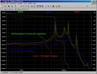
For an example, I have just similated in LTSpice my LCRLCRLCR power supply, comparing the frequency response of (1) (Green) Reservoir capacitors without snubber; (2) (Blue) Reservoir capacitors with a single 0.1uF + 1R snubber, assuming inductance of 50nH; and (3) (Red) Reservoir capacitors with a single 0.1uF + 1R snubber, assuming inductance of 350nH.
As you can see from the graph, the reservoir capacitor LCR resonances are in the lower MHz region, which is not unreasonable.
But the 50nH and 350nH inductance of the 1R resistor makes a huge difference. With 350nH (0.35uH, which is the 1R metal film resistor I measured) the snubber hardly works.
I know the similation is not accurate. But the resonance effects it indicates are probably real, with differences of possibly different magnitude or at different frequencies.
Attachments
Last edited:
Lead inductance of a through hole package is of the order of 25nH, SMD around 10nH or less.
The lead inductance is relatively small. The resistor internal has much higher inductance if it is the wound type.
Can you share the models you used for your parallel reservoir caps ?
Also for a snubber the resistor does not dissipate too much. So you can use some cheap 1206 SMD film resistors, maybe several in parallel.
There are also high power thin films but you will need lots of copper area on your PCB to cool them (or some sticky thermal pads and a small heatsink).
This style can be epoxied to some cooling mass.
There are also the TO-220 resistors.
Last edited:
How about using a bunch of smaller resistors in parallel? This will reduce the inductance. I don't know how this compares in price to a fancy low-inductance resistor, but it's something that could be done by anyone.
Yes, and that is why I bought the 2W 22R metal film for the usually 5W 8R zobel resistor. Unfortunately, each 22R resistors measures 4.6uH so if I parallel 3 of them to get 6W 7.1R, I will get about 1.5uH. This is as high as the output inductor!!!!!

Last edited:
Can you share the models you used for your parallel reservoir caps ?
Also for a snubber the resistor does not dissipate too much. So you can use some cheap 1206 SMD film resistors, maybe several in parallel.
There are also high power thin films but you will need lots of copper area on your PCB to cool them (or some sticky thermal pads and a small heatsink).
This style can be epoxied to some cooling mass.
There are also the TO-220 resistors.
There are some choices for SMD. For through hole, I found nothing.
Attached is the LTSpice model. I don't trust the result but it still indicates the problems. Other than 2 x 10,000uF at the third position, all other reservoir caps consists of parallelling 680uF 100V low ESL capacitors in power / ground planes. The LCR values may look very strange but they are designed for the lowest and equal current passing through the inductors so that I can be sure that the inductors are not saturated to generate harmonics. I have previously tried to use inductors and found they all failed due to saturations.
Attachments
Can you share the models you used for your parallel reservoir caps ?
Also for a snubber the resistor does not dissipate too much. So you can use some cheap 1206 SMD film resistors, maybe several in parallel.
There are also high power thin films but you will need lots of copper area on your PCB to cool them (or some sticky thermal pads and a small heatsink).
This style can be epoxied to some cooling mass.
There are also the TO-220 resistors.
Have you used them before?
If the back plate is sodered on the ground plane to dissipate heat, I suspect that capacitance to ground may be high. But then perhaps it does not matter if it is used for MOSFET source resistor or Zobel.
They are expensive! Even if I buy quantity of 50, I will still need to pay $3 for each, something like that.
True, but I don't expect low Ohm value metal film or metal oxide to be anything like as high as the measurements above. If they were, it would be impossible to make a video or RF amplifier.The lead inductance is relatively small. The resistor internal has much higher inductance if it is the wound type.
[...], I will get about 1.5uH. This is as high as the output inductor!!!!!
Doesn't this give you the chance to remove the inductor from the output and use the inductance of the resistor (which is there anyway) instead?
Rundmaus
Your inductance results look a bit high to me. Measuring small inductance values is not easy - getting a number on a screen is easy, but it may contain no significant figures.
Even if your figures are correct, the question to ask is "at what frequency does this resistor begin to look more like a lossy inductor?" Note that in some cases (e.g. grid stoppers) a lossy inductor may work just as well as a resistor.
Even if your figures are correct, the question to ask is "at what frequency does this resistor begin to look more like a lossy inductor?" Note that in some cases (e.g. grid stoppers) a lossy inductor may work just as well as a resistor.
Have you used them before?
Yes, but not for audio. It was the flat film type resistor, about 1cm2 in size. I epoxied it to the chassis for cooling. Works pretty well. As a source resistor, on second thought, maybe the capacitance could be a problem.
If you want a low inductance medium power resistor at bottom prices, lots of 1c SMD resistors in parallel is hard to beat...
Doesn't this give you the chance to remove the inductor from the output and use the inductance of the resistor (which is there anyway) instead?
Rundmaus
Then the inductor would be inside the feedback loop, and may make stability worse. There is also the fact that in the class A conduction region there will be half the inductance, but in the class B region there will be the total inductance of one resistor. The feedback loop must be either extremely fast or very slow for this to work. I think the OptiMos is in the latter category, but I would not bank on it. Not only that, but inductors radiate.
Hi, DF96 and David,
You are probably right that the values I measured may be on the high side. But even if they have been doubled the values are still too high.
The LCR metre I use (DM4070) has a specification of 0.1uH with an accuracy of 2.5%.
I had a keen diyAudio forum member who measured many resistors for me last night comparing his numbers to mine after he read this thread. His numbers are in average smaller than mine but not significantly so. He uses a different LCR metre with frequency up to 100kHz that has a specification of 0.001uH with error of 1% (I really don't know how one can achieve that as the wire length is at least in the range of 0.01uH).
I wouldn't mind if they were lossy inductors (working like ferrite?) but how do I know?
If you want a low inductance medium power resistor at bottom prices, lots of 1c SMD resistors in parallel is hard to beat...
I would have a headache to solder a single SMD wearing my glasses in addition to a magnifying glass and now I need to parallel many of them?
- Status
- This old topic is closed. If you want to reopen this topic, contact a moderator using the "Report Post" button.
- Home
- Design & Build
- Parts
- Low inductance resistors for power amp - some measurements