Experience with both. If you look at that resistor closely, note the screws used to tap across the resistive plates (if copper plates can be called resistive). At high slew rates, those taps with the wire pair connected to them, will intercept magnetic field from the tap wire loop to the center of the resistor, causing a phase shift in the signal. I used a 250 micro-ohm one a while ago, it was about a foot long, 4 inches by 4 inches, with 11 plates 1/16 thick about 7 or 8 inches long. At 6 kiloamps 60 hz, there was a 1.5 volt error signal due to magfield trapping. I dropped that to about 10 millivolts by running the tap return wire down the geometric center of the plates. While the current I used was large, it scales to 20Khz audio quite closely. 20,000/60 = 333, 100wrms into 8 ohms is 5 amps, 5/6000 times that is .27. So 100wrms at 20Khz into that 250 u Ohms will give about .5 volts error, while the resistive signal is .00025 * 5, or 1.25 millivolts. So the error is 400 times larger than the signal.You must work @ Gov / MIL industrial complex LOL
Big hole in the ground under Switzerland maybe?
Went there a few times. Spent a week there assisting them after they had that little "incident" 2 weeks after startup. Seems they needed soldering advice..
Brilliant!!! This should be a Guinness World Record.
So far, they've not contacted me..
I am sure soldering 40 resistors to make a single resistor can work like a dream but unless I want to build a rocket or something I am not prepared to go that length, given that I can find some SMD power resistors that has virtually no inductance, such as the link I posted earlier.
The problem you are going to have is not related to the unit per se, but rather, the loop formed by the unit between the current within it and the return current.
If you wish rather low inductance, take a copper braid and pull it over an axial metal film resistor, using it as the return current path of the resistor. That will confine the magnetic field generated by the resistor to under the braid. This is how coax works.
The interleaving structure I've created is not limited to 40 resistors. I designed it to be scaleable. Anywhere from 4 resistors to thousands. To calculate the effective inductance, use these assumptions:
One pair will have 200 nH per foot L, 1/4 inch long will have 200/48, or 5 nH per.
4 pairs will have 5/4, or 1.25 nH. 20 pairs, .25 nH, or 250 picohenries.
This is an approximation, it also includes a factor for the plates and the area spreading. Very important is having the device exit leads very close together.
jn
Last edited:
I design my circuit board to use power / ground planes and make sure high current paths have return paths on large areas of copper on the other side of the PCB. For current paths outside the boards I use twisted pairs.
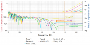
I think it is still important to have low inductance of the Rsource, Rzobel and Rsnubber. Take the 7.5R 6.6W wirewound resistor I measured with 7uH. That is equivalent to a straight, round copper wire of 1mm diameter for the length of 4 metres! Of course, that may be an extreme. If we take the 3 x 22R 2W metal film for the Zobel which has 1.5uH, that is about one metre wire. If we take the 0.22R source resistor inductance of the non-inductive wirewound of 0.2uH, that is about 18cm wire.
I played with line level regulators a lot powering opamp circuits. I knew if I used a 10cm wire to connect the PSU to the load the sound can be degraded significantly.
I understand that this is in RF territory. But I believe that RF noise in the audio circuit affects the audioband. My Marantz UD7007 blu ray player uses SMPS PSU which generates a lots of noise at 100kHz and also beyond 1-10MHz, measured with my 100MHz scope. When I reduced the noise by using heavy duty LCR filtering as well as ferrite, the sound was much improved.
Last edited:
Thanks.cool idea anyway, I like it
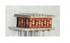
The beautiful thing is, the two plates where the two terminals collect every other lead can be two sides of a double sided PC board. I only have single sided perf, so needed two plates. In your rotated pic, the bottom plate can be made double sided. The resistor leads in the top plate can be bent over to suspend the resistors, and the top board can be lifted a tad so that the resistors that connect to the top board layer will form a fillet that is visible. Or, the top board can be soldered tin/silver and the bottom lead/tin, for a simple step soldering process.
jn
Last edited:
I forgot to mention..
If you notice in the pic, half the resistors are upside down w/r to the others, simply because I oriented them like that based on the color code striping. If you replaced all the resistors in the array that have the black band down with a resistor of a much larger value, like 99 for example, you'll have a 100:1 ladder divider, the top plate being the center node. This scheme would make for a totally non inductive feedback divider in a power amp.
jn
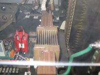
I used a 250 micro-ohm one a while ago, it was about a foot long, 4 inches by 4 inches, with 11 plates 1/16 thick about 7 or 8 inches long. At 6 kiloamps 60 hz, there was a 1.5 volt error signal due to magfield trapping. I dropped that to about 10 millivolts by running the tap return wire down the geometric center of the plates.
Ah, finally found the picture. Sorry it's so fuzzy, it's through a 1/4 inch lexan blast shield..
If you look carefully, you can see the tap wire start at the far side, go into the plate assembly, resurface closest to the camera, then go over to where the other tapped hole is for the voltage wire connections.
The tap wire was tinned solid copper with clear teflon tubing over it.
jn
Attachments
Low-inductive power resistors for emitter, Zobel and output coil. https://ro.mouser.com/datasheet/2/219/BPR-944283.pdf , https://ro.mouser.com/datasheet/2/303/res_10-1265495.pdf
Last edited:
- Status
- This old topic is closed. If you want to reopen this topic, contact a moderator using the "Report Post" button.
- Home
- Design & Build
- Parts
- Low inductance resistors for power amp - some measurements