Can you parrallel Bridge Rectifiers and Voltage Regulators to handle more current.
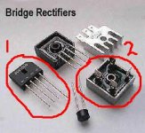
As far as the rectifiers I want to use the ones like "1" in the picture, cause there easy to mount on a PCB, whereas the "2" can handle 20-30 amps no problem, but they are awkward to mount.
Then for the regulators, I can't seem to find any that are rated for more than 1 or maybe 2 amps, so I was wondering if you parrallel them, can you get them up to like 4 or 5 amps.
Of course I understand that parralleling stuff can cause problems, especially when dealing with high current.
Attachments
heat is the key....
It is not practical to parallel rectifiers. The current will never be shared equally.
The reason for the construction differences it the heat that is generated and needs to be "lost".
Schottky diodes have less voltage drop and so generate less heat. You will probably be able to find PCB mount Schottkys with the current ratings you need. They still need heatsinking when run hard.
Regulators can be parallelled if fitted with current sharing components. The current rating can also be boosted by using an external series pass device, usually a FET.
This subject has been debated ad nausium on other threads.
ehhh the common voltage regulators like the 7812 etc. have another type that can handle 3A...I remeber seeing them around On-Semi's webby...I will get back as soon as I found out what's the part No.
Update: It's the 78T12 on their Webby...here's a link
http://www.onsemi.com/site/products/searchresults/0,4533,,00.html?searchString=78t12
Update: It's the 78T12 on their Webby...here's a link
http://www.onsemi.com/site/products/searchresults/0,4533,,00.html?searchString=78t12
They're meant to be mounted on a heatsink, and hard-wired.Hybrid fourdoor said:So how exactly are you supposed to mount those big bridge rectifiers? I usually just stick them upside down.
Rectifiers can be paralleled..but there is a thermal runaway issue.
In the standard 3 phase mil bridge product I was involved with, the six branches were composed of three diodes in parallel. But, for stability, each diode was binned during test for Vf within one millivolt.
The second thing that has to happen is each has to see the exact same thermal connection to the outside world. That way, each heats up exactly the same amount. If one heats up more, it's vf will drop more, and it will then hog all the current. (thermal runaway)
The third thing is the electrical resistance in series with each diode. Each diode must see the same voltage drop..kinda like a ladder, with the rungs as diodes..if you push current from one end only, the "rung" closest to the end will pull more current..but, if you run the current in one end of the ladder, and out on the other end, each "rung" will see the same.
Honestly, the bigger chassis mounted option is the best...certainly the easiest..
Cheers, John
Another option is to make a bridge up of 4 schottky rectifier diodes. Like the MUR series from ON semi, in case you choose that option, its just a matter of overkill, then you can keep them on the pcb.
I though agree with peranders....the bridges meant for the purpose are .......you guessed right.....made for the purpose")
To go overkill schottky may save you some heat though.
Magura
I though agree with peranders....the bridges meant for the purpose are .......you guessed right.....made for the purpose
To go overkill schottky may save you some heat though.
Magura
Paralleling mode you can to use only with discrete diodes ( with low value resistor connected in series with each diode ), what is similar to paralleling of transistors in power amp ( local negative feedback ). But all is nonsens now, because are maded bridge rectifiers with 35 A current with wire connection ( for example by International Rectifier ), with inrush current of several hundred amperes.
- Status
- This old topic is closed. If you want to reopen this topic, contact a moderator using the "Report Post" button.
- Home
- Design & Build
- Parts
- Parralleling Rectifiers and Voltage Regulators