In the power supply of my DAC I tried as a primary capacitors borrowed from a friend Nichicon FW - 5pcsx2200uF/35V on each polarity of the supply voltage and stayed very satisfied with the result. Then I decided to purchase my own FW's but they offered me KW as FW were out of stock. Here: Miniature Type Aluminum Electrolytic Capacitors Nichicon state the KW are with "improved sound quality" compared to FW. So I choosed to purchase few pcs of 10 000uF/50V KW assuming I'll get better quality than what I got from the FW's because of the "improved sound quality" and the higher rated voltage @the same uF value. After continuous working for 3-4 days I put my new KW's under listening test to experience a big disappointment - the 10mF/50V KW's sound noticeably worse than the 5x2200uF/35V FW's... Now I'm confused - do KW's need more working time to settle to its best performance or I'm just ****** up following and trusting Nichicon guidelines...
Does anybody have any experience and impressions with the KW series?
Does anybody have any experience and impressions with the KW series?
I mean, I relied to what is stated here.
http://s11.postimg.org/nkbj9p89v/kw_to_fw.jpg
So far I do not notice KW higher sound quality than FW despite all manufacturer claims...but exactly the other way around!
Anybody capable to share such experience?
http://s11.postimg.org/nkbj9p89v/kw_to_fw.jpg
So far I do not notice KW higher sound quality than FW despite all manufacturer claims...but exactly the other way around!
Anybody capable to share such experience?
Last edited:
Regardless of whether the claim of 'better sound quality' is real or not, there are basic engineering issues involved here. A power supply capacitor for a DAC will be presented with high frequency ripple from the DAC chip, probably somewhere in the 10MHz region. So, the impedance of the cap at 10MHz may be far more important than the actual value of capacitance, usually quoted for 120Hz. If the cap has a higher impedance, then the ripple generated by the DAC will not be attenuated as much.
The original cap, an FW 2200uF/35V is packaged in a case that is 16mm x 25mm. The new KW 10,000uF/50V cap is packaged into a case that is 25mm x 50mm. Without actually measuring the cap or seeing published impedance vs. frequency curves, it is still safe to say that the KW cap will have a higher impedance above 1MHz than the original FW simply because the electrodes are larger. In theory, this could lead to worse performance.
What would be a better approach is to try a 2200uF KW series cap, and parallel a smaller 10-50uF (at twice the actual PS voltage) solid tantalum or solid aluminum chip across that, and also parallel a small monolithic ceramic cap around 0.1uF-1uF. In this way, you are creating a composite capacitor that will behave like the 2200uF cap at low frequencies, but as the large electrolytic becomes inductive at high frequencies and its impedance rises, it is shunted with the smaller solid electrolytic. At still higher frequencies, when the solid electrolytic becomes inductive, the ceramic cap will take over, probably well past the operating frequencies used in the DAC. This approach will make the cap more electrically ideal at all important frequencies, and should improve sound quality in a meaningful way.
Best of luck!
Last edited:
It doesn't matter what you use at that value, it will be worthless at MHz frequencies. As above, you need smaller value bypass caps that are almost certainly present at the chips already. Lead length is a killer for HF bypass. Even the short leads of an axial part, no matter how good the part itself is, make it worthless for HF bypass use. That's why SMT bypass caps are so superior, and why you need ground planes for HF circuits.
You say this is in the power supply so I assume it's 50/60 cycle filtering. The only thing that matters there is the actual value, which determines ripple. If it's a switching supply, then other things like esr do matter. Knowledge of manufacturers sound claims (IMO, all meaningless) and the listening delay in changing out parts probably negates any listening test. In this case, a high speed scope would be more useful.
You say this is in the power supply so I assume it's 50/60 cycle filtering. The only thing that matters there is the actual value, which determines ripple. If it's a switching supply, then other things like esr do matter. Knowledge of manufacturers sound claims (IMO, all meaningless) and the listening delay in changing out parts probably negates any listening test. In this case, a high speed scope would be more useful.
Last edited:
I decided that I must share my final conclusions after the very first disappointing impressions from my new KW series from Nichicon.
Briefly - it took at least 2 weeks (!) of constant working to start giving me the sound quality that I paid for. Even now they go on improving their exceptionally nice sound performance. And now KW are really far from FW as to sound quality. The very first words that came into my head after listening to them again were: they play with exceptional ease. Voices and acoustic instruments are reproduced with natural ease and lightness like a breath of a child. KW present a nice merit - very high detail without being annoying.
And the main conclusion I made for myself from this is: the higher the sound quality of the parts the longer the time the parts take to settle to its best performance.
Last edited:
An alternative explanation is that your ears have taken a while to get used to a slight reduction in sound quality. A component (apart from a transducer) does not have a 'sound quality'; a component in a circuit might have, depending on how the component properties match the circuit requirements. A perception of 'detail' can sometimes be a symptom of HF noise.
This explanation has nothing to do with the real situation because the capacitors were left for 2 weeks in my radio shack connected to 30VDC and every 3-4 days I checked what happened with them. And I explain how do "they sound" now because I put them in a very well known CDP where if I replace a sound critical component it is easy to distinguish the new component sound behavior.
And in my humble practice I have noticed that the HF noise/RF interference as a rule leads to muddy and low resolution sound. Getting measures to clean up the RF interference from the critical analog parts and PS especially contributes to the clean detailed sound.
And in my humble practice I have noticed that the HF noise/RF interference as a rule leads to muddy and low resolution sound. Getting measures to clean up the RF interference from the critical analog parts and PS especially contributes to the clean detailed sound.
Last edited:
Regardless of whether the claim of 'better sound quality' is real or not, there are basic engineering issues involved here. A power supply capacitor for a DAC will be presented with high frequency ripple from the DAC chip, probably somewhere in the 10MHz region.
No it will not.
A properly designed circuit will have, starting from the device power pin :
- enough ceramics for local decoupling, perhaps also a low-impedance polymer
- then a ferrite bead to prevent noise from contaminating the main power rail
- main power rail will have some HF decoupling too
The big capacitors we're talking about are far, far away from this mess and normally do not see any HF noise. They are useless at HF anyway. Those big caps don't go past 10-20 kHz. Their purpose is energy storage.
If there is some HF noise on the main power supply caps and it comes from the digital chips (ie, you see some 128Fs ripple on the scope) then you're in for a lot of trouble, as this basically means the entire board is soaked in noise. Remember, you cannot "upgrade" the layout...
When doing a layout, no effort should be spared to keep HF currents inside smallest possible loops. For example I have a 5x10 cm board with 4 DC/DC converters running at 250kHz, currents are 1-2 amps, 10ns switching, there is also a H-bridge and some other stuff, and the current sense amp, monitoring a 30mV voltage on a current shunt... I get less than 1 LSB of noise on this (10 bit ADC), so less than 30µV input referred noise... I bet the opamps in lots of digital audio gear have more noise than that :mrgreen: !! The opamp has a DC-DC switcher 1cm to the left, a h-bridge 1cm to the right, a 16 MHz microcontroller 1 cm below, and runs on the same power rail from the 5V switching converter feeding everything (MOSFET drivers, uC, even some boost converter feeds from this 5V)... I'd bet the 5V supply on that opamp is still cleaner than what powered the opamps on that CD63SE back in the day...
The board is standard 2 layer. There are caps and ferrites everywhere. Actually there are probably more ceramic caps than all other components combined, which is the way it should be... At the beginning this board didn't work, the bug was 5mm of shared trace which shouldn't have been shared...
Please post several photos of the device, schematics if you have them, etc... Scope shots of what's on those supply caps are a plus (DC couple, and also highpass filter with 10nF/100 ohms and X10 probe, short ground lead).
Last edited:
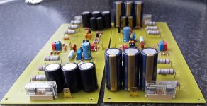
If size matters this is the size difference in Nichicon KW vs Panasonic FC.
They are 3x 470uF 100V per rail.
Regards
Which one do you prefer for power supply?
I'm recapping a Nuance Famco preamp, ordered Panasonic FC to replace all small electrolytes. As for the 2200uf/50v, I can't find any Panasonic FC at a reasonable price.
I do find Nichicon FW. I wonder if they're supposed to "sound" as good as the Panasonic FC, or should I insist on FC or any better model. The Nichicon FW are 85c.
Thanks
I do find Nichicon FW. I wonder if they're supposed to "sound" as good as the Panasonic FC, or should I insist on FC or any better model. The Nichicon FW are 85c.
Thanks
Last edited:
Many thanks for sharing this information ! While looking for information on good capacitors to replace those in my good Chinese power supplies for my 3 band active filter, I came across this post of yours. So I replaced the four main 4700uf 50v and a few additional 33 and 22uf with Nichicon KW series. Honestly, I didn't expect any audible change, but I can't leave otherwise the good power boards with Chinese electrolytes. Then, according to your recommendation, I left the filter permanently plugged in with a voltage of 13 volts ds. For the first few days I almost couldn't hear a change in the sound, then after the sixth day I hadn't played the system and what can I say after playing the music on the tenth day! I can't believe that such a change is possible with the replacement of some capacitors. For the money I spent, this is the most sensitive change I have heard in my system. It's like when I gave up trying passive filters and heard my system with the very good active one I made. Now I'm afraid that I will have to replace the filter capacitors on my 3 stereo amplifiers ( Rod Elliott P101 ) with Nichicon KG series....)
Many thanks again and best regards too !!!
Many thanks again and best regards too !!!
- Home
- Design & Build
- Parts
- Nichicon KW vs FW. Confusing impressions...