Hi gang, I'm building a U47 clone and decided to be an audiophool and get some high-end caps.
We have 3 caps: a .01uF V-cap TFTF; a .1uF V-cap OIMP, and a 1uF Mundorf Silver/Gold Oil cap:
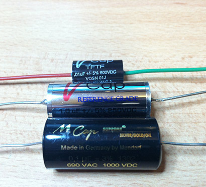
So I wanted to pre-burn these babies in before installing them in the mic I'm building. I read Jim Williams of Audio Upgrades suggested a 10K square wave at 10V into a 100R resistor. Since some of these caps take hundreds of hours to burn in, and since I'm using 50-year old vacuum tubes that I'd rather not put those kind of hours on, I'm pre-burning them in.
So here's the results of an oscilloscope test. The top image is the square wave input. These are actually 3 different outputs so even though they look identical, I'm including them for honesty's sake:
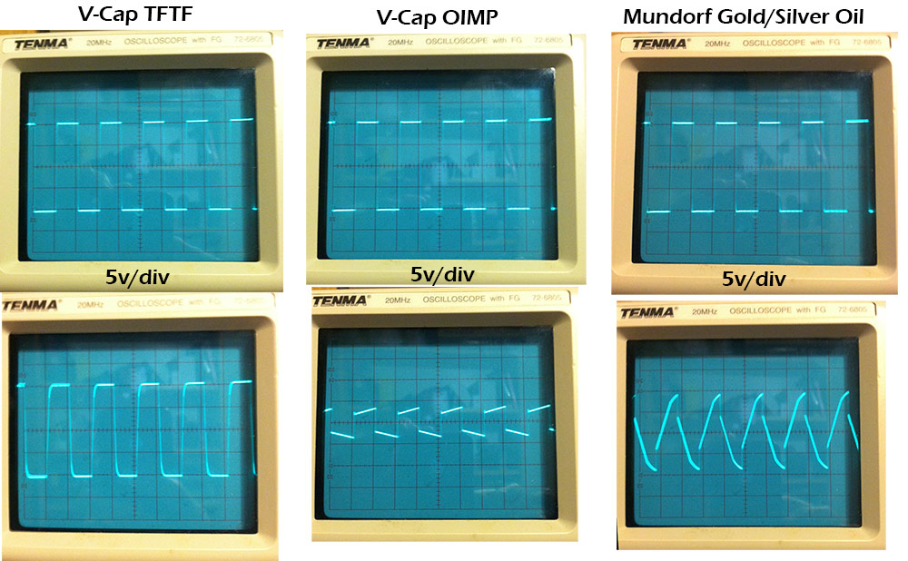
Guys, I'm no EE (my dad is), and perhaps I don't know what the f I'm doing. But can anyone explain why in cat's heaven the V-cap OIMP and the Mundorf are destroying the input signal, and the V-cap TFTF (teflon) are not? Could it have anything to do with the value of the caps...same 10v square wave driving each one.
If the OIMP and the Mundorf really are destroying signals like that, could they be damaged caps, or is this what they actually do to a signal? Why would anyone ever use anything but the teflons then...
Thoughts please? Be kind. I'm no electronics genius.
Thanks,
Mike
PS all caps are brand new from the factory. Also if you like GroupDIY I posted it there too.
We have 3 caps: a .01uF V-cap TFTF; a .1uF V-cap OIMP, and a 1uF Mundorf Silver/Gold Oil cap:
So I wanted to pre-burn these babies in before installing them in the mic I'm building. I read Jim Williams of Audio Upgrades suggested a 10K square wave at 10V into a 100R resistor. Since some of these caps take hundreds of hours to burn in, and since I'm using 50-year old vacuum tubes that I'd rather not put those kind of hours on, I'm pre-burning them in.
So here's the results of an oscilloscope test. The top image is the square wave input. These are actually 3 different outputs so even though they look identical, I'm including them for honesty's sake:
Guys, I'm no EE (my dad is), and perhaps I don't know what the f I'm doing. But can anyone explain why in cat's heaven the V-cap OIMP and the Mundorf are destroying the input signal, and the V-cap TFTF (teflon) are not? Could it have anything to do with the value of the caps...same 10v square wave driving each one.
If the OIMP and the Mundorf really are destroying signals like that, could they be damaged caps, or is this what they actually do to a signal? Why would anyone ever use anything but the teflons then...
Thoughts please? Be kind. I'm no electronics genius.
Thanks,
Mike
PS all caps are brand new from the factory. Also if you like GroupDIY I posted it there too.
Last edited:
Since I'm pretty well entrenched in camp of the people that you told to "go away", and I don't know the exact circuit and conditions that you are using to test your capacitors, I don't feel that I'm qualified to reply.
However... what would be really interesting, would be to see those scope traces under the exact same conditions after hundreds of hours of "burn in".
However... what would be really interesting, would be to see those scope traces under the exact same conditions after hundreds of hours of "burn in".
But can anyone explain why in cat's heaven the V-cap OIMP and the Mundorf are destroying the input signal, and the V-cap TFTF (teflon) are not?
I understand you are not an EE, or even remotely aware of electrical theory, but still: do you think it's reasonable to compare widely varying capacitances in your setup?
What you get is normal capacitor behaviour. It has nothing to do with the type of dielectric or price.
The burn-in won't change these pics at all.
Last edited:
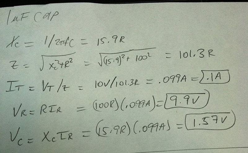
Sorry, I'm not "remotely unaware of electrical theory" - I have taken the entire undergrad core in physics including electricity with good grades - 20 yrs ago. I don't appreciate the dig. I understand Ohm's law, and after some posts at groupdiy.com I spent time looking things up. Here's my calcs - go ahead find the errors.
Here's the site I found for understanding it:
Series RC Circuits
Please, let's keep this forum in a spirit of fun and learning. I refuse to be afraid to post before spending an hour looking up equations. It's posts like that, that make forums suck.
Maybe it's time to retire.
Night all.
Here's the site I found for understanding it:
Series RC Circuits
Please, let's keep this forum in a spirit of fun and learning. I refuse to be afraid to post before spending an hour looking up equations. It's posts like that, that make forums suck.
Maybe it's time to retire.
Night all.
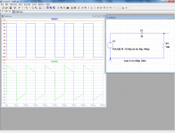
This is what you should see, no matter which capacitor you plug in: with this set-up, the cheapest and lousiest mylar will give the same visible result as the most expensive fused silica lab standard:
The variations you observe either mean you're making something completely wrong in your measurement, or all of your boutique caps are complete crap (or both)
The variations you observe either mean you're making something completely wrong in your measurement, or all of your boutique caps are complete crap (or both)
Attachments
Relax. You are the one who first said you were no EE, so what are we to assume then? And you are the first one to take a dig at people who think differently in your opening post, so...
IN any case, you present three caps. One is a 0.01uf, one is a 0.1uf, and one is a 1.0uf, at least as far as I can tell from your description. Unless I missed something, why would we expect the three caps to react the same when each is different from its neighbor by a factor of 10 in capacitance?
I suppose your calculations work for your 1uf cap. Now go do them for the other two values. yes, value matters. A good example of mattering is the caps in your speaker crossovers. Change the value, change the frequency.
I don't know those caps, I am not into that, but look up the data sheets on each. Aside from capacitance, you might see what they show for ESR and things like self-inductance.
I think it is dangerous to over-generalize attitudes about caps. It is not black and white. I wouldn't argue against better quality caps sounding better in some way. But then I probably would not agree that $100 caps are better than $10 caps.
We have 3 caps: a .01uF ; a .1uF , and a 1uF cap:... a 10K square wave at 10V into a 100R resistor.
...I'm no EE (my dad is), and perhaps I don't know what the f I'm doing. But can anyone explain why in cat's heaven
Ask your Dad about rise time of an RC circuit. Or visit wikipedia.
Hint -you've got 100:1 difference in capacitance and time constants that neatly bracket a 10kHz square wave.
I assume that you are measuring the voltage across the capacitor in your test.
If so then the 0.01uF is as expected but the two larger ones are exhibiting high impedance effects due to series inductance within the capacitor. The 1uF one should show a triangular (ish) waveform of reduced amplitude if it is presenting a low impedance to the higher harmonics of the square-wave. Wound foil types with few connections to the foils do tend to exhibit large inductance, the better performing ones have all the turns connected at each end.
With the higher impedances involved in a valve amplifier then the effect may not be as pronounced as you are seeing. Try the same with a 100K resistor and you may get a more "text book" waveform.
I tried a cheap and cheerful 1uF 1000V capacitor from RS and it did produce the expected triangular waveform.
I agree capacitors do not need burning in, they will not improve no matter how long you keep then with a signal applied.
Risking being unpopular by saying:- if expensive capacitors sound better maybe they are just producing a more acceptable form of distortion?
Thanks Enzo - point taken, I was a bit gruff in the opening. Thanks Elvee, Arno, thoglette, John8: thank-you; excellent points!
...sq225917, haha! I know they're not electrolytics.
Enzo, I was measuring them wrong - I was measuring across both R and C. After much googling I see how to do it across the cap only. I also had the R attached to the (-) to ground, instead of having the cap leg to ground.
I did not mean to come across as crass, so apologies, and thanks for the support.
I am concerned there may be something wrong with my 'scope, but as I continue to upgrade my understanding it may be me all along. I get that since the cap values are the same, the waveforms will be totally different. In my initial haste I just didn't stop to think.
Thanks all for the thoughts.
Mike
Last edited:
By the way, who says you can't hear an expensive capacitor? I dropped one today. Boy I heard it!
Try blind-testing
")
I should not really be posting in a thread where the OP says from the beginning that I am not welcome, but I suggest you relabel the 'scope pictures with cap value rather than brand - as that will highlight the only relevant factor to the entirely predictable results you see. You could then ask why do different cap values behave differently, but then we would have to talk about circuit theory and time domain CR response rather than brands.
But thanks, anyway, for making me smile.
But thanks, anyway, for making me smile.
Thanks.
There may be minor differences in response between different caps with the same value but different constructions, but you would need much more complex instruments to see this. You would then find that the cap dielectric and construction method was of greater importance than brand, except for those cases where the brand is an indicator of poor construction (despite high cost) or even fakery. Try Googling for Cyril Bateman's cap tests.
There may be minor differences in response between different caps with the same value but different constructions, but you would need much more complex instruments to see this. You would then find that the cap dielectric and construction method was of greater importance than brand, except for those cases where the brand is an indicator of poor construction (despite high cost) or even fakery. Try Googling for Cyril Bateman's cap tests.
- Status
- This old topic is closed. If you want to reopen this topic, contact a moderator using the "Report Post" button.
- Home
- Design & Build
- Parts
- What the ? - Odd Capacitor Results