Such as how to tell if they are electrolytic or not. Yea that's the main thing, so lets talk about how many different types of caps there are in say a integrated tube amp, such as a Scott 299 since that is what I am working on. The big cans which I assume are for the power supply were missing or broken off, so I followed the schematic, and some stuff I read off line and replaced them. I am under the impression since this thing is old the electrolytic caps need to be replaced how do I know which ones those are since there are some different looking ones per say.
I don't want to go into a Scott rebuild here as this forum is intended for parts, but would like to know what replaces what. Plus I think it would help other newbies such as me. Maybe we can have a cross reference on caps and resistors. I now have figured out carbon comps vs metal film I think, but am still quit unsure. There just seems to be too many options for these things.
Thanks
It's easy to spot electrolytics in tubular aluminum "cans", ranging roughly 1/2" to 2" diameter and 1-1/2" to 6" tall. They are usually secured to the chassis or circuit card assembly by twisting, or bending over, small metal "ears" that go through slots in the chassis or board. The aluminum casing is almost always the negative terminal, though occasionally you might find one where both the " + " and " - " terminals are electrically isolated from the case. The most common use for these is power supply filtering.Electrolytic caps will have one lead designated as the negative lead , most other types of caps will be bipolar , most caps in a tube amp that are over 1uF will usually be electrolytic , the big metal multi caps are electrolytic ......
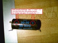
The atch photo shows the other style of electrolytic you may encounter. Note that it has polarity marking - though some manufacturers only mark the " + " terminal. This style is commonly used as the cathode bypass capacitor or possibly the filter in a bias supply. The actual capacitor is also enclosed in a tubular aluminum can, but a cardboard sleeve is wrapped around the can so the construction isn't obvious at first glance. Nevertheless, you might encounter an electrolytic capacitor like this without the sleeve, just the naked aluminum tube. The value and polarity markings could be applied with ink, or stamped into the aluminum.
Dale
Attachments
A search engine reveals several schematics for that unit on the 'net, but apparently there were several versions. Post a link to the schematic you're working from and we can call out the reference designators for the electrolytic capacitors.Can you post a few photos of your amplifier, it will be easier for us to point out what components are what from some photos.
Dale
You can identify the electrolytics on the schematic diagram, see the symbols on this link. Note the + marking is not always indicated on the diagram itself.
Capacitor symbols | schematic symbols
Capacitor symbols | schematic symbols
This is all good info everybody, when I get home tonight I will try and grab a picture of the whole unit. As for the schematic I am using, its a photo copy. Mine has the single 160 ohm 20 watt wire wound resistor instead of the 2 330 ohm 10 watts in parallel.
oshifis, that is a good link thanks for sharing.
I think I have a little better understanding on caps. I will have to do the obvious and research what electrolytic means, maybe I am looking at it all wrong.
oshifis, that is a good link thanks for sharing.
I think I have a little better understanding on caps. I will have to do the obvious and research what electrolytic means, maybe I am looking at it all wrong.
This is the schematic that looks like mine.
http://oldtech.net/HHScott/299.gif
If I got this strait if there is a +/- it probably is a electrolytic, what about the I kind of figured power supply caps/cans were electrolytic.
What are coupling caps and how are they identified.
http://oldtech.net/HHScott/299.gif
If I got this strait if there is a +/- it probably is a electrolytic, what about the I kind of figured power supply caps/cans were electrolytic.
What are coupling caps and how are they identified.
It appears at a glance that the only other caps you need to address are the cathode bypass caps - 25uF @ 25V and there are only two of those.
If those are the ones coming off 2 of the 12ax7 sockets then that has been done as one of the cans up front were replaced and when I did I used a sprague can with I think 100 ufs and ran a bypassed 25 uf cap off of the lug on the sockets that had been originally wired to the multi-section can that was originally there.
Now going through the schematic and high lighting the ones I think are electrolytic and the ones I think are electrolytic are.
c201-210, c126, c128, c26, c28. If someone can confirm these are in fact all electrolytic that would mean the rest aren't which is making sense. If that is the case then I do have most of the electrolytic's replaced other then a couple here and there I need to go through and find.
c201-210, c126, c128, c26, c28. If someone can confirm these are in fact all electrolytic that would mean the rest aren't which is making sense. If that is the case then I do have most of the electrolytic's replaced other then a couple here and there I need to go through and find.
Serious eyestrain here. but...
Thats what I was thinking.
godfrey said:I doubt C26, C28, C126 and C128 are electrolytic. They're only 0.1uF and need to be high voltage, low leakage. I'd expect them to be plastic film caps.
I think this is what I ordered some high voltage caps for yes either plastic film or ceramic disc. Wonder why I only purchased 2 and not 4 hmm.
That's a good place to start, but I wish the symbols shown in that link were truly "standard". I have seen too many exceptions to rely on the curved line indicating an electrolytic, versus two straight lines indicating a non-polar capacitor. In MOST cases a capacitor with explicit polarity markings is some kind of electrolytic construction (either aluminum, or tantalum) but I briefly worked at a place where a lazy draftsman used the same identical symbol - with the " + " sign - for ALL capacitors.You can identify the electrolytics on the schematic diagram, see the symbols on this link. Note the + marking is not always indicated on the diagram itself.
Capacitor symbols | schematic symbols
Dale
Let's see if my eyeball scan produces the same laundry list as others. The electrolytics are :
C15, C115 (Ref des uncertain - on cathode of V102-A)
C201, C202, C203, C204, C205, C206, C207, C208, C209, C210, C211, C212, C213, C214
In your tube amp, the main "coupling caps" are the signal path between the plate circuit of one stage and the grid circuit of the following stage. Also, between a signal input connection and the first stage, or between the last stage and a signal output connection.What are coupling caps and how are they identified.
C1, C2, C6, C8, C9, C12, C13, C14, C20, C25, C26, C28, and their corresponding counterparts on the "B-Channel" side of the amp.
(OK, to a purist some of these aren't "coupling caps" per se, but part of response-shaping or filtering circuits for tone control, signal enhancement, etc. If you want to quibble over definitions like this, pick a fight with somebody else.)
Some capacitors from that era, built with paper insulators impregnated with oil or wax, become leaky and/or lossy over time and are prime candidates for replacement. The degradation of electrical characteristics may not be as dramatic as with electrolytics, and some types may be "as good as new" half a century later - though the "like new" performance is still less than a modern, high-quality film cap.
The very low-value capacitors - in the 10's or 100's of picofarads range - are likely to be some kind of mica construction, and can be expected to last a few milleniums if they haven't been electrically or thermally abused.
Dale
If those are the ones coming off 2 of the 12ax7 sockets then that has been done as one of the cans up front were replaced and when I did I used a sprague can with I think 100 ufs and ran a bypassed 25 uf cap off of the lug on the sockets that had been originally wired to the multi-section can that was originally there.
They are labeled C15 and C115 in the schematic you linked.
- Status
- This old topic is closed. If you want to reopen this topic, contact a moderator using the "Report Post" button.
- Home
- Design & Build
- Parts
- Identifying different types of caps