I wonder if they cleaned the old joint properly first. Solder contaminates from leads and pcb plating very quickly. 63/37 is far more tolerant than most lead free alloys.
Who knows? This was just some neurotic audiophile who I'm sure would have "heard" a difference even if he had simply been told that one of the joints was reflowed.
se
Just use some 63/37 solder and be done with it or 62/36/2 if you absolutely can not live without silver in your solder.
Sonic differences between solders? Not bloody likely.
People who can "hear" differences between solders are either idiots or audiophiles and the line between those 2 groups is very thin.
Sounds harsh? Sure, but there is some truth to it.
Sonic differences between solders? Not bloody likely.
People who can "hear" differences between solders are either idiots or audiophiles and the line between those 2 groups is very thin.
Sounds harsh? Sure, but there is some truth to it.
It does worry me, the claims that some can hear, I recently got told on a thread to train my ears so I could to hear the difference between a standard crystal and a TCXO...
Personally though I prefer SMD resistors as the lead weld on through hole components I find adds a certain dullness to the sound...
Personally though I prefer SMD resistors as the lead weld on through hole components I find adds a certain dullness to the sound...
It does worry me, the claims that some can hear, I recently got told on a thread to train my ears so I could to hear the difference between a standard crystal and a TCXO...
Personally though I prefer SMD resistors as the lead weld on through hole components I find adds a certain dullness to the sound...
if you can "really" hear the difference between leaded and unleaded solder...use the silver one! other way do not waist your time thinking of it.
I bet you will never notice the sound between them. if you ask me...you can "clamp" the components and I will never hear the difference in sound lol.
I bet you will never notice the sound between them. if you ask me...you can "clamp" the components and I will never hear the difference in sound lol.
Personally though I prefer SMD resistors as the lead weld on through hole components I find adds a certain dullness to the sound...
Personally I prefer through-hole carbon comp resistors as there is no lead weld nor a nickel barrier plating as there is on SMD devices. Just tin coated copper wire.
se
Personally I prefer through-hole carbon comp resistors as there is no lead weld nor a nickel barrier plating as there is on SMD devices. Just tin coated copper wire.
se
Thru-hole non magnetic, all the way. Enough mass and size to have excellent balance in thermal dynamics, in signal creation, handling and propagation of the complex field. SMD is thin sounding and un-dynamic, at best.
Thru-hole..not too big, as the field has to be catered to and the overall noise characteristics, as well. It's a fine balance. 1/4 watt, TO-92, and so on. Stray too far from that and the balance shifts.
Some folks mistake the thin-ness of the sound produced by SMD as fidelity when it is not. It is just a thin balance in the sound, which emphasizes the upper mids and low treble as being balanced and fleshed out, when in fact it is just that emphasis, and the rest being lost. Learning to hear that can take some doing. Being aware of it helps. Some of it is capacitive coupling that smears and covers up fine detail and is mistaken in its grossness and coarseness as being detail.
Also, when we got into audio, our collective and individual audio mamma's taught us to NEVER, EVER put a component in direct contact with a board. NEVER. This should not be done as it couples the fields to the substrate and we find that our sound now resembles the urine-poor capacitance of the board material and any traces beneath, and what not. Disturbingly, in the direction of SMD sound qualities. That the field development in the upper frequencies is turned to some form of fecal matter with direct contact. With thru-hole resistors, they should each be about 1.5-2 mm above the surface of the board. Rigidly mounted and away from the board. Not too far, to maintain rigidity and not too close, to avoid coupling. How many of you remembered? Or where even taught and aware of this critical aspect?
We were told this way back at the beginning of our audio journey. It was critical to never forget this.
SMD circuits will earn you a smack in the back of the head from your audio momma, that will knock your teeth loose.
Last edited:
Yet SMD circuits will do for some of the most sensitive analogue designs on the planet.
Also, when we got into audio, our collective and individual audio mamma's taught us to
As to the rest, a lot of Audiophile myth, never mind the minimal signal lengths you can achieve with SMD...Thermal engineering easier with SMD components as well these days with modern packages.
And again, I would bet a lot of money that NO ONE could distinguish between solders in a listening test.
Cardas solder is overpriced for what it is, more Audiofoolery. considering the millions of solder joints made in the world every day, and how important these joints can be, there is no lack of information out there regarding soldering, without having to create any myths about it. NASA, Nation Physics Lab, IPC all have extensive studies regarding soldering and joint formation, and the importance of the intermetallics formed, also its reaction with various fluxes and with PCB surface finish (another important aspect).
Steve, can beat that, pure copper trace resistors, recently had to do a 22ohm resistor on a board using the copper trace, area 15mm x 50mm track length 2m (a heater element for a Laser, to avoid 0 degrees temps, so mostly works at very low temp, aids heat dissipation, at 30 deg C 5V the track would burn out).
Also, when we got into audio, our collective and individual audio mamma's taught us to
???????, consider the distance the signal travels down traces on a PCB, travelling through the dielectric, cant see how this can have any effect on signals in the audio range.Also, when we got into audio, our collective and individual audio mamma's taught us to NEVER, EVER put a component in direct contact with a board. NEVER. This should not be done as it couples the fields to the substrate and we find that our sound now resembles the urine-poor capacitance of the board material and any traces beneath, and what not. Disturbingly, in the direction of SMD sound
As to the rest, a lot of Audiophile myth, never mind the minimal signal lengths you can achieve with SMD...Thermal engineering easier with SMD components as well these days with modern packages.
And again, I would bet a lot of money that NO ONE could distinguish between solders in a listening test.
Cardas solder is overpriced for what it is, more Audiofoolery. considering the millions of solder joints made in the world every day, and how important these joints can be, there is no lack of information out there regarding soldering, without having to create any myths about it. NASA, Nation Physics Lab, IPC all have extensive studies regarding soldering and joint formation, and the importance of the intermetallics formed, also its reaction with various fluxes and with PCB surface finish (another important aspect).
Steve, can beat that, pure copper trace resistors, recently had to do a 22ohm resistor on a board using the copper trace, area 15mm x 50mm track length 2m (a heater element for a Laser, to avoid 0 degrees temps, so mostly works at very low temp, aids heat dissipation, at 30 deg C 5V the track would burn out).
Cardas solder is overpriced for what it is, more Audiofoolery.
And of course these are the same folks that like to plate everything with rhodium. That might be fine for mechanical contacts, but it's a horrible material to solder to.
Steve, can beat that, pure copper trace resistors, recently had to do a 22ohm resistor on a board using the copper trace, area 15mm x 50mm track length 2m (a heater element for a Laser, to avoid 0 degrees temps, so mostly works at very low temp, aids heat dissipation, at 30 deg C 5V the track would burn out).
HA!
Ok, got me beat. But how do you pull off a 10k or 100k without using a crapload of board space? Also, how do you keep inductance down? I suppose you could use vias and do a Ayrton-Perry geometry of sorts.
se
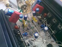
See this? All done with lead-free solder. With the proper temperature and technique, there is practically no difference between lead-free and lead solder. Lead-free smells better perhaps, but that's it.
Now Google "tin whiskers."
se
Larger Values would be impossible, and current capacity is very limited, you have to use 4 thou track and gaps, 1/2oz copper or lighter. I attempted a 1k and gave up, but tried using some ideas from mazes to get the most contiguous length of track in the smallest space, but also have a repeatable pattern, a fractal autorouter would help.
Chartres and other church mazes
Tin whiskers, a big problem for high rel products even when you can use tin/lead solder, most modern components have a Pb free finish on the terminals...
I use Multicore Tin/Lead/silver, because I have a big roll of it
Chartres and other church mazes
Tin whiskers, a big problem for high rel products even when you can use tin/lead solder, most modern components have a Pb free finish on the terminals...
I use Multicore Tin/Lead/silver, because I have a big roll of it
The wetting of solder has nothing to do with the temperature of the solder.
It has everything to do with the flux, both it's activity and it's working temperature range, as well as the surface cleanliness, and the surface type. Some fluxes are better suited for some metals, nickel for example has one flux that's better than most.
RMA flux has historically used zinc chloride..I understand Kester is now using something I can't pronounce..abba....abba...abba something..
Tin whiskers are an issue if a short caused by them cannot clear it. Toyota had this issue according to a nasa report.
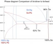
Tin pest doesn't seen to be an issue for tin/silver eutectic. I used about half a ton, it all is at liquid helium temperature, and no pest so far.
Can't say if whiskers grow in tin/silver however. 7000 amp busses tend to clear whiskers, so if they grow, they don't survive.
Me, for hi rel, it's tin/lead eutectic all the way.
edit: oops, this must be an earlier version of my slide presentation, that 232 C is the melt temp of pure tin, for some reason the drawing is messed up..sorry.
jn
It has everything to do with the flux, both it's activity and it's working temperature range, as well as the surface cleanliness, and the surface type. Some fluxes are better suited for some metals, nickel for example has one flux that's better than most.
RMA flux has historically used zinc chloride..I understand Kester is now using something I can't pronounce..abba....abba...abba something..
Tin whiskers are an issue if a short caused by them cannot clear it. Toyota had this issue according to a nasa report.
Tin pest doesn't seen to be an issue for tin/silver eutectic. I used about half a ton, it all is at liquid helium temperature, and no pest so far.
Can't say if whiskers grow in tin/silver however. 7000 amp busses tend to clear whiskers, so if they grow, they don't survive.
Me, for hi rel, it's tin/lead eutectic all the way.
edit: oops, this must be an earlier version of my slide presentation, that 232 C is the melt temp of pure tin, for some reason the drawing is messed up..sorry.
jn
Attachments
Last edited:
Larger Values would be impossible, and current capacity is very limited, you have to use 4 thou track and gaps, 1/2oz copper or lighter. I attempted a 1k and gave up, but tried using some ideas from mazes to get the most contiguous length of track in the smallest space, but also have a repeatable pattern, a fractal autorouter would help.
Chartres and other church mazes
Tin whiskers, a big problem for high rel products even when you can use tin/lead solder, most modern components have a Pb free finish on the terminals...
I use Multicore Tin/Lead/silver, because I have a big roll of it
Must be quite popular with the babes.
se
Me, for hi rel, it's tin/lead eutectic all the way.
Yup. The stuff just works wonderfully well. And RoHS can just kiss my... backside (God I hate that idiotic nanny filter here, wish the Powers That Be would grow the !@#$% up).
se
Last edited:
bought a small 100gr roll lead free, with silver, to try it first
havent used it much, but appears like it gets rather 'hard' when soldered
and does not feel good to solder more than once
I suppose I will have to take the chance to inhale a bit more lead fumes
The safety guys here measured the fumes in the soldering operations here. Bench with pencils, solder pots, the induction soldering line, and individual cartridge heater soldering fixtures. They indicated no trace of lead, just lots of fumey type stuff.
Since HCl is a byproduct of the zinc chloride deconstruction as it were, I'd certainly avoid breathing that stuff if at all possible.
jn
- Status
- This old topic is closed. If you want to reopen this topic, contact a moderator using the "Report Post" button.
- Home
- Design & Build
- Parts
- Leaded or unleaded solder ?