Two ways to approach this issue, but Borbely confuses them.
1. Treat the interconnect as an audio transmission line. It will have a characteristic impedance which is high, reactive and frequency dependent over most of the audio range. Therefore you can't terminate it with a resistor as its characteristic impedance is not resistive. It will also have a frequency dependent propagation speed. Fortunately none of this matters because it is also very short in wavelength terms so you can just treat it as a low value resistor in series, with a low value capacitor to ground. The correct way to feed this network is from a low impedance, with a highish impedance load. Funnily enough, this is what sensible people have always done.
2. Treat the interconnect as an RF transmission line, and an audio signal as a sum of impulses. The usual terminations will then cause lots of signal reflections which will die away exponentially at a rate determined by the cable and terminations. However, the input signal is band-limited (all audio signals are band-limited) and the receiver has one or more low pass filters (all audio amps are low pass filters). Hence all the signal reflections will not be visible or audible; just compare the period of a 20kHz wave (50us) to the round trip delay on a 1m interconnect (around 10ns). Even 100's of reflections will do no harm, except to introduce a little delay - which can be calculated by using method 1 above.
If I were wiring a theatre or stadium I might start to think about this issue, and wonder whether I needed to add compensating inductors to the cables to reduce frequency dispersion - as used to be done on trunk telephone lines. For a short interconnect in my lounge I know that the quasi-static EM approximation is perfectly good enough so I can treat the cable as a resistor and a capacitor. This is first-year electromagnetism.
Merlin give it a rest mate you are getting on my nerves, have a look at the use of numerous famous an infamous people whos names are used as a reference or an indication for other stuff. there is nothing contentious about it so go get a life and get of my back mate. OK GOT THAT
DF96 you forgot skin effect! tut tut
Oh I've also referenced Oliver Heaviside in my replys, I was also not being disrespectful to him, hough there have been numerous references to some of the seminal work he did on the problems (imagined for audio frequencies) we are discussing.
Now if I seem to be getting grumpy its cos I have a Pavlovian reaction to pathetic criticism.
Last edited:
When I want 'surreal' I think Monty Python rather than Dali.
Magritte.
Merlin give it a rest mate you are getting on my nerves, have a look at the use of numerous famous an infamous people whos names are used as a reference or an indication for other stuff. there is nothing contentious about it so go get a life and get of my back mate. OK GOT THAT
DF96 you forgot skin effect! tut tut
Oh I've also referenced Oliver Heaviside in my replys, I was also not being disrespectful to him, hough there have been numerous references to some of the seminal work he did on the problems (imagined for audio frequencies) we are discussing.
Now if I seem to be getting grumpy its cos I have a Pavlovian reaction to pathetic criticism.
Forgive me cos Dali was Catalonian like I'm.
Two ways to approach this issue, but Borbely confuses them.
1. Treat the interconnect as an audio transmission line. It will have a characteristic impedance which is high, reactive and frequency dependent over most of the audio range. Therefore you can't terminate it with a resistor as its characteristic impedance is not resistive. It will also have a frequency dependent propagation speed. Fortunately none of this matters because it is also very short in wavelength terms so you can just treat it as a low value resistor in series, with a low value capacitor to ground. The correct way to feed this network is from a low impedance, with a highish impedance load. Funnily enough, this is what sensible people have always done.
2. Treat the interconnect as an RF transmission line, and an audio signal as a sum of impulses. The usual terminations will then cause lots of signal reflections which will die away exponentially at a rate determined by the cable and terminations. However, the input signal is band-limited (all audio signals are band-limited) and the receiver has one or more low pass filters (all audio amps are low pass filters). Hence all the signal reflections will not be visible or audible; just compare the period of a 20kHz wave (50us) to the round trip delay on a 1m interconnect (around 10ns). Even 100's of reflections will do no harm, except to introduce a little delay - which can be calculated by using method 1 above.
If I were wiring a theatre or stadium I might start to think about this issue, and wonder whether I needed to add compensating inductors to the cables to reduce frequency dispersion - as used to be done on trunk telephone lines. For a short interconnect in my lounge I know that the quasi-static EM approximation is perfectly good enough so I can treat the cable as a resistor and a capacitor. This is first-year electromagnetism.
I'm sure Erno not confuses.
Not hugely relevant, but can be included when calculating the resistance of the cable. Net result is that the audio characteristic impedance gets slightly different frequency dependence, because R varies as well as L and C. For the RF view, skin effect increases attenuation so making transients decay more quickly which makes the Borbely model even sillier.marce said:DF96 you forgot skin effect! tut tut
Please explain why you think he is not confused. Your answer should be based on the science of transmission lines, not personalities (Catalonian or otherwise).merlin el mago said:I'm sure Erno not confuses.
I was concerned that you might want to quote a guru, as some do on here.
To drive a 'low impedance' line (it actually isn't low impedance at audio frequencies, as I have explained, but the termination certainly is) with a -6dB attenuation gives slightly poorer signal-noise ratio and probably higher distortion because you need a power driver. If this seems to you to be an improvement then fine. No simulations are involved; just science.
To drive a 'low impedance' line (it actually isn't low impedance at audio frequencies, as I have explained, but the termination certainly is) with a -6dB attenuation gives slightly poorer signal-noise ratio and probably higher distortion because you need a power driver. If this seems to you to be an improvement then fine. No simulations are involved; just science.
Merlin, how do you drive such low impedances?
Opamps are ruled out. Most of the buffers too. I'm aware of only one buffer which could drive such load, but it cost quite a lot for an IC, and is out of production. TO-3 cased LH0063...
Alternatives...
- LME49600
- Opamp-wrapped BUF634/AD815...
Opamps are ruled out. Most of the buffers too. I'm aware of only one buffer which could drive such load, but it cost quite a lot for an IC, and is out of production. TO-3 cased LH0063...
Alternatives...
- LME49600
- Opamp-wrapped BUF634/AD815...
Last edited:
Baffled
I enjoy learning, exactly what is it that you are measuring and how do I interpret
the Scope images ?
If there is something noticable to ears, it cold be seen on measurement equipment.
I enjoy learning, exactly what is it that you are measuring and how do I interpret
the Scope images ?
I use Erno Borbely stuff I/V DAC, lineamp/headphone amp and 75W RMS monobolocks amps. I'm using balanced with two separate PSU and two stereo preamps in two chassis (one for 2 PSU and the other chassis for the 2 preamp)
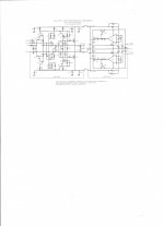
Preamp topology
"The input JFET-Cascode, consisting of Q1-Q2-Q3 and Q4 are operated at 2 mA. Q1 and Q2 have to be matched to 10% of Idss. The second stage, consisting of JFETs Q6-Q9 and MOSFETs Q7-Q8, are operating at just below 10mA. Q6 and Q9 have to be selected for Idss>10mA. Note that this also provides matching between the N- and P-channel JFET. The output devices: Q10-Q11 are Hitachi TO-220 MOSFETs. They are operating at approx. 70mA; proper heat sinking is therefore mandatory.
Q5 is a JFET-input servo amplifier, providing tracking of the output offset to less than 1mV. The RC-networks of R10-C6 and R11-C7 filter out all AC signals over 1 Hz. The servo is therefore only operational at less than 1 Hz, and should not affect the sound of the amplifier. Nevertheless, if you feel that it does, don’t hesitate to try different opamps for this. D1 and D2 are IC shunt regulators, supplying Q5 with +-10 Volt."
Merlin, how do you drive such low impedances?
Opamps are ruled out. Most of the buffers too. I'm aware of only one buffer which could drive such load, but it cost quite a lot for an IC, and is out of production. TO-3 cased LH0063...
Alternatives...
- LME49600
- Opamp-wrapped BUF634/AD815...
Borbely 116 lineamp schematic
An externally hosted image should be here but it was not working when we last tested it.
Attachments
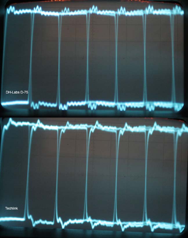
Here is the picture of Dune HD Base 3.0 media player SPDIF out with cheap cable (7€) vs DH-Labs D-75:
An externally hosted image should be here but it was not working when we last tested it.
And what exactly are you seeing that will make any difference? Anything on the scope above/below threshold (like all the garbage on the top and bottom) makes NO difference to the sound. Please learn about digital electronics.
cbdb, D-75's slew rate seems a bit faster. Does it mean something to you?
Oh, headphone amps... Yep, that's what they are - a good line drivers.
- Status
- This old topic is closed. If you want to reopen this topic, contact a moderator using the "Report Post" button.
- Home
- Design & Build
- Parts
- Looking for silver digital coax