I recently got a couple of Ward Beck VU meters that came with these rectifier (?) boards. These look really simple in comparison to other buffer/rectifier circuits I've seen pictures of, so my first question is: Am I right in saying these don't have a buffering component to reduce noise coming back into the signal? If not, it's alright since I will be using a dedicated output to provide signal to these meters. I've already tested them by sending a 1kHz -20dBFS tone and both meters lined up close to 0dBVU, so I know I'll need to adjust the trimmer to get them calibrated eventually.
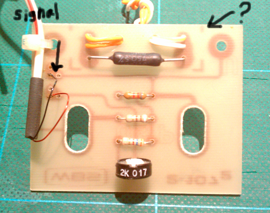
There's a 75ohm resistor here that doesn't appear to connect to the circuit, can anyone tell me what it's for?
The meters each have two lamps at the bottome, but then again I have a ton of multicolored LEDs with proper resistors for 9v power, so I'm thinking of making a circuit for the LEDs and adding a switch for a 9v battery pack (thought it would be cool to have an on/off switch for just the lights), but I'm curious to know if the board is capable of providing power to the lamps (I have no idea how much power they need, they were not connected to the board and each have three wires that were clipped off, different color wires than what you see above connecting to that 75ohm resistor).
Thanks in advance for any help with this.
No rectifier. Your meter circuit has three resistors and a trim pot. The meter movement this would have been mounted on is simply a volt meter. The resistors are across that and set the range, the trimmer is to set the meter to calibration. The meter with little circuit board would have been part of a larger system. ANy buffering would have been there. There is nothing of that sort here.
Then the rectifier has to be built into the VU meter, because I've fed signal to the meters with the cards attached and the needle only swings towards the right. These came off a Ward Beck console, so who knows if it even had a buffering amp circuit.
Can anyone else help me figure out what the 75ohm resistor that's not connected to the circuit is for?
Can anyone else help me figure out what the 75ohm resistor that's not connected to the circuit is for?
Looking at the 75 ohm resistor, and we can see the circuit board traces through the board, it looks unrelated to the metering function. If I had to guess, I;d say it was involved with the meter illumination circuit. I am making this up, but for example a 24v supply, and the resistor drops that for use by some lamps in the meters. You may have lights with other color wire, but that doesn't mean they all didn;t get wired to a common terminal strip somewhere.
I worked at Ward Beck for a little while.
Yes the board is fed from a meter amplifier located elsewhere in the console.
Most of the circuits ran off 20 to 24 rails with local regulation on each board. The lamps for the meters ran off the raw higher voltage rails.
Yes the board is fed from a meter amplifier located elsewhere in the console.
Most of the circuits ran off 20 to 24 rails with local regulation on each board. The lamps for the meters ran off the raw higher voltage rails.
Last edited:
I worked at Ward Beck for a little while.
Yes the board is fed from a meter amplifier located elsewhere in the console.
Most of the circuits ran off 20 to 24 rails with local regulation on each board. The lamps for the meters ran off the raw higher voltage rails.
Very cool, thanks for the info. Last night while doing more research on Ward Beck and these meters, I found the Ward Beck Preservation Society: Ward-Beck Systems Preservation Society -------------------------------------------------------------------------------------------------------------------- WBSps.ca - Ward Beck, WBS, Ward Beck Modules, Gallery, APK audio
They've got a ton of WBS schematics there, I found a .pdf on the meters which I believe are the ones I have, except the circuit mentioned along with the meters is an amplifier, thought I would share: http://wbsps.ca/PDFs/Ward-Beck Systems - M435-436 - VU Meter - www.WBSps.ca.pdf
I have no idea how/if the above applies to the cards I got on my meters, but hopefully someone might find it helpful!
True "VU" meters always contain rectifiers and are spec'd for ballistics and often a standard absolute signal level of 0dBu with series 3600 Ohm resistor to read 0VU.
Full scale, VU, and average signal level are three different things - related, but quite different.
Your -20dB full scale and the meter's 0VU are not directly correlated. You must *define* your 0VU and your peak to average ratio first. You may, for example , decide that -20dB full scale *is* 0VU. Or not.
All good fortune,
Chris
Thank you, one is a bit closer to 0vu than the other; I don't know what -20dBFS would be in analog but whatever that is, that's what these meters are currently calibrated to.
I'll most likely calibrate to -18, but it would be great if I could have more than one option, via switch. Would that be possible using the card above?
I'll most likely calibrate to -18, but it would be great if I could have more than one option, via switch. Would that be possible using the card above?
...a more focused question for what I'm trying to do would be:
What would I need to do to have a variable level switch for this meter? I was thinking an input pad (possibly 2 attenuated steps or maybe more depending on the work needed). Would I need an input attenuator before the meter circuits (and figure out how much drop at each step)?
What would I need to do to have a variable level switch for this meter? I was thinking an input pad (possibly 2 attenuated steps or maybe more depending on the work needed). Would I need an input attenuator before the meter circuits (and figure out how much drop at each step)?
- Status
- This old topic is closed. If you want to reopen this topic, contact a moderator using the "Report Post" button.
- Home
- Design & Build
- Parts
- I need help with this Ward Beck VU circuit