") What is '43' wire used for? I guess to get gain I should connect the input to single +? What is " - - " used for?
What is '43' wire used for? I guess to get gain I should connect the input to single +? What is " - - " used for?The primary has two sections which you normally have connected in series. If you want to get gain you basically have two options - either use half and leave the other one flapping in the air or have the two paralleled. Turns out (surprise!) that opinions on which way sounds better differ.
43 - this circuit uses a switch with more positions than the 102 - i think the extra ones they use for mute.
43 - this circuit uses a switch with more positions than the 102 - i think the extra ones they use for mute.
I don't have the 102s but I've built an autoformer attenuator, so I think I can answer some of your questions:
> What is '43' used for
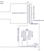
I think he left 43 out because he's using a 23 position switch, and he wants one position for mute (i.e. shorted to ground). So he's hooked it up for 2dB steps from 0 through -40dB, then 6dB steps to -46 and -52, and then mute. If your switch has more positions, I don't see why you couldn't use the -43dB tap. I think the missing text says something like "Use -43 if you don't want mute".
Likewise, if your switch has less positions, you'll have to pick which of the dB taps you need. Which is trial and error, or calculating the gain structure of the rest of your system and figuring out how much attenuation you need. I usually set it up for fine control (i.e. 2dB/step, that's the finest you can go) in 2 regions, one for normal listening and one for late-night listening, and coarse control (4/6/8dB per step) in between. Of course, that means that every time I change my amp or speakers, I have to re-do this. My unit has 3dB steps and I have a 12-position switch, and with my previous amps I had it set to 0, -3, -6, -9, -12, -18, -24, -30, -33, -36, -48, -54. You get the idea - closely bunched in the 0 to -12 and -30 to -36 ranges, further apart for the rest.
> Also, how to get gain on that thing?
If you connect the input across +6 and ground on the primary, that should get you half the primary windings, which would give you double the voltage output. Note that this halves your current output, or looking at it another way, the 'reflected' output impedance of the source device is now 4x what it was (impedance changes by square of turns ratio). Thus, if you use this in a step-up situation, you'll lose a lot of drive. Whether that'll hurt or not depends on the rest of the system, I think. In my experience, these things sound better when they're stepping down. Ideally, stepping way down, because then all your input voltage is converted to output current. (Which is different from a pot - those sound better when turned up, I think, but these sound better turned down.)
Hope that helps. I don't know what - and -- are for.
> What is '43' used for
I think he left 43 out because he's using a 23 position switch, and he wants one position for mute (i.e. shorted to ground). So he's hooked it up for 2dB steps from 0 through -40dB, then 6dB steps to -46 and -52, and then mute. If your switch has more positions, I don't see why you couldn't use the -43dB tap. I think the missing text says something like "Use -43 if you don't want mute".
Likewise, if your switch has less positions, you'll have to pick which of the dB taps you need. Which is trial and error, or calculating the gain structure of the rest of your system and figuring out how much attenuation you need. I usually set it up for fine control (i.e. 2dB/step, that's the finest you can go) in 2 regions, one for normal listening and one for late-night listening, and coarse control (4/6/8dB per step) in between. Of course, that means that every time I change my amp or speakers, I have to re-do this. My unit has 3dB steps and I have a 12-position switch, and with my previous amps I had it set to 0, -3, -6, -9, -12, -18, -24, -30, -33, -36, -48, -54. You get the idea - closely bunched in the 0 to -12 and -30 to -36 ranges, further apart for the rest.
> Also, how to get gain on that thing?
If you connect the input across +6 and ground on the primary, that should get you half the primary windings, which would give you double the voltage output. Note that this halves your current output, or looking at it another way, the 'reflected' output impedance of the source device is now 4x what it was (impedance changes by square of turns ratio). Thus, if you use this in a step-up situation, you'll lose a lot of drive. Whether that'll hurt or not depends on the rest of the system, I think. In my experience, these things sound better when they're stepping down. Ideally, stepping way down, because then all your input voltage is converted to output current. (Which is different from a pot - those sound better when turned up, I think, but these sound better turned down.)
Hope that helps. I don't know what - and -- are for.
- Status
- This old topic is closed. If you want to reopen this topic, contact a moderator using the "Report Post" button.