Hello, I have little knowledge of transformers.
I am looking to use a transformer to amplify a voltage of 1V-3V rms at 200KHz to something like 30V rms at 200KHz. Current consumption expected to be approx 100mA - 300mA.
I am not sure what type of transformer to use, how many turns on the primary/secondary and what diameter wires .
Any help appreciated.
I was looking for basic design/shopping options - eg iron core or air core, toroidal or E shape (I am not sure about the names) etc.
Bandwidth - frequency will be fixed at 200KHz. Amplitude will also be fixed at the appropriate level. Isolation not necessary as the primary will be in the order of a few Volts and the secondary again a few tens of Volts. I am not sure about the rest of the parameters, eg leakage currents and paracitic capacitances.
Bandwidth - frequency will be fixed at 200KHz. Amplitude will also be fixed at the appropriate level. Isolation not necessary as the primary will be in the order of a few Volts and the secondary again a few tens of Volts. I am not sure about the rest of the parameters, eg leakage currents and paracitic capacitances.
A readily available Ferrite RM core or small EFD or ETD core transformer will work. At 200kHz then the standard power ferrite grades used for SMPSU transformers such as N67, N87, 3C91 or 3F3 will all do a good job.
I guess there will be no dc current flowing in the transformer? In this case you can use an ungapped core. Have a look at Farnell or RS to see what ungapped RM10 core and bobbins they have. As an alternative you could salvage a suitable core set and bobbin from a scrap SMPSU. Have you calculated what inductance you will need on the transformer windings?
Although your application is for a sine wave (I guess), this on-line SMPSu resource might help.
Design of switch power supplies
Iron core not the best for losses at that frequency, requires thin lams
toroids are worst for pri-sec parasitic C, can be painful to wind by hand
look ar Sw mode PS transformer design info - ferrite pot cores are better at self shielding come with standard bobbins, clamping, mounting hardware
DC on pri would be a limiting issue with material selection - no problem as long as AC coupled
quite a few sw converter xfmrs are now stock items - searching for adequatly speced part may take some time, depending on how close you want, easier if high "overkill" ratio not a problem
As you are asking a very generic question, here is a starting point.
Buy Transformers and Ferrite Kits & Cores RM 10 coil former, 12 pin power Epcos B65814C1512T1 online from RS for next day delivery.
The formulae for calculating the number of turns have been iterated more times on this forum that I guess to remember.
Buy Transformers and Ferrite Kits & Cores RM 10 coil former, 12 pin power Epcos B65814C1512T1 online from RS for next day delivery.
The formulae for calculating the number of turns have been iterated more times on this forum that I guess to remember.
I am making a device which is not related to audio and not related to PSUs.
I am making this device for my own personal use.
I am not 100% certain about the device description yet, but I have a rough idea. I will need to experiment to get more information.
I have worked "backwards" and I decided I needed to use a transformer. Obviously this may not be the right thing to do - but it is a start.
A general description is this:
The device must produce an output of 200KHz sinusoidal at a peak of 50 Volts. The output of the device will be applied onto a unit which may have a resistance of about 400-800 ohms (this is not verified yet). The unit measures approximately 15 cm - 20 cm and an electric field of 1V-2V / cm must be created. The electrodes of the device will be attached to the unit via two pads which will also present their own resistance, may be 100Ohms on each pad (this is not verified yet as the pad material has not been chosen yet).
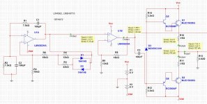
So far I have created one module: a 200KHz sinusoidal generator producing 4.2V peak into a load of 5 Ohms. The explanation is:
The generator is a Wein bridge using an dual audio op-amp LM-4562 where the first op-amp generates the 200KHz and the second op-amp amplifies/buffers it to get a final 4.2V peak (2.97V RMS). There is also a transistor push-pull stage to allow us to drive 2-5 Ohms.
Now all that remains is to transform the 4.2V peak into 50V peak. For that I would need a transformer with turns ratio of approx 12. That means that the load on the secondary, a worst case hypothetical 400 ohms (not verified yet) will be reflected back to the primary as 400 / 12^2 = 2.82 Ohm.
So my first stage has to be able to drive a 2.82Ohm load at 200KHz and at 4.2 V peak.
Now comes the selection of the transformer.
The transformer is needed because the device is powered by 2 6V batteries - therefore creating a +/- 6 V supply.
So far I know that the transformer needs to have a turns ratio of 12, work at 200KHz sinusoidal and drive a load of 400 Ohms at the secondary.
I am not sure about the power of this transformer, but I tell you I tried my device on a 5 Ohm resistor (to simulate driving the transformer) and both the resistor and the output transistors get very hot (must use bigger heatsinks).
If you can tell me what transformer I need and so on you'd save me a lot of reading")
I am making this device for my own personal use.
I am not 100% certain about the device description yet, but I have a rough idea. I will need to experiment to get more information.
I have worked "backwards" and I decided I needed to use a transformer. Obviously this may not be the right thing to do - but it is a start.
A general description is this:
The device must produce an output of 200KHz sinusoidal at a peak of 50 Volts. The output of the device will be applied onto a unit which may have a resistance of about 400-800 ohms (this is not verified yet). The unit measures approximately 15 cm - 20 cm and an electric field of 1V-2V / cm must be created. The electrodes of the device will be attached to the unit via two pads which will also present their own resistance, may be 100Ohms on each pad (this is not verified yet as the pad material has not been chosen yet).
So far I have created one module: a 200KHz sinusoidal generator producing 4.2V peak into a load of 5 Ohms. The explanation is:
The generator is a Wein bridge using an dual audio op-amp LM-4562 where the first op-amp generates the 200KHz and the second op-amp amplifies/buffers it to get a final 4.2V peak (2.97V RMS). There is also a transistor push-pull stage to allow us to drive 2-5 Ohms.
Now all that remains is to transform the 4.2V peak into 50V peak. For that I would need a transformer with turns ratio of approx 12. That means that the load on the secondary, a worst case hypothetical 400 ohms (not verified yet) will be reflected back to the primary as 400 / 12^2 = 2.82 Ohm.
So my first stage has to be able to drive a 2.82Ohm load at 200KHz and at 4.2 V peak.
Now comes the selection of the transformer.
The transformer is needed because the device is powered by 2 6V batteries - therefore creating a +/- 6 V supply.
So far I know that the transformer needs to have a turns ratio of 12, work at 200KHz sinusoidal and drive a load of 400 Ohms at the secondary.
I am not sure about the power of this transformer, but I tell you I tried my device on a 5 Ohm resistor (to simulate driving the transformer) and both the resistor and the output transistors get very hot (must use bigger heatsinks).
If you can tell me what transformer I need and so on you'd save me a lot of reading
A readily available Ferrite RM core or small EFD or ETD core transformer will work. At 200kHz then the standard power ferrite grades used for SMPSU transformers such as N67, N87, 3C91 or 3F3 will all do a good job.
I guess there will be no dc current flowing in the transformer? In this case you can use an ungapped core. Have a look at Farnell or RS to see what ungapped RM10 core and bobbins they have. As an alternative you could salvage a suitable core set and bobbin from a scrap SMPSU. Have you calculated what inductance you will need on the transformer windings?
Although your application is for a sine wave (I guess), this on-line SMPSu resource might help.
Design of switch power supplies
Thanks for that.
Yesterday I found a few RM10 cores and bobbins in my drawer , I wound 10-11 turns enamel for the primary and 100+ turns for the secondary (got bored and stopped counting after a while). I then put the whole thing together and held the two halves with electrician's tape.
By testing Vp and Vs on no load, it seems I have wound a ratio of 1:10 rather than the 1:12 as I should have (next time I will count).
I have also checked and the transformer is not getting hot (or even warm) but I have ordered digital thermometers to make sure.
Is there an *easy* way to combine (a) frequency (b) power (c) with/without DC component to be able to arrive at the size of the core needed, eg RM8, RM10, RM12 etc?
"Have you calculated what inductance you will need on the transformer windings?"
No, I have no idea how to do that. Is there an easy way to calculate it ?
Last edited:
Find the 'Ferroxcube' app note called "soft Ferrites and Accessories" on the web. I think the latest version is the 2009 one. In this you will find a set of graphs for the different type of cores showing the gap size required for a given I^2 x L for the different sizes of that core. So if you knew that your peak I might be 1A (as you have no dc flowing) and your required inductance was 2mH (say), then your I^2 x L would be 2mJ. Simply look up on the graphs what core size is appropriate.
The required primary inductance is the same as for any other transformer. Make it high enough that your magnetising current at the operating frequency is very low compared with the current actually providing the real ouput power.
The required primary inductance is the same as for any other transformer. Make it high enough that your magnetising current at the operating frequency is very low compared with the current actually providing the real ouput power.
Hi. I have been reading but still have tons of questions.
I have used an RM10 with AL = 4500nH, me=1650, gap=0, length = 44.6 mm and area = 96.6 mm^2.
I have wound 10 turns of 18 AWG wire on the primary and 100 turns of 30 AWG (or even thinner) on the secondary.
I have used it under these conditions and it seems "OK".
F = 200KHz pure sinusoidal
primary : 2.5 V RMS
secondary : 25 V RMS @ 50 mA RMS
However given what I have read so far, I *think* I should have started by doing core power calculations and then the number of primary turns and so on.
So what I need is a tool to input the requirements and get the necessary info on cores to use ( effective area and length, permeability, flux (the AL value whatever that is), the wires to use and the number of turns
If its not overheating then you are below the magnetic saturation of the core which is good.
Good design normally keeps the core flux below 1000mT (320mT is used by the military for reliability)
Irrelevant of the core, the windings must be capable of the currents involved.
Good design normally keeps the core flux below 1000mT (320mT is used by the military for reliability)
Irrelevant of the core, the windings must be capable of the currents involved.
Last edited:
Hi again. What you say makes sense. I know I have 10 turns on the primary and 100 turns on the secondary, so according to AL=4500nH I should be reading 0.45uH for the primary and 45uH for the secondary - which is very close what I have just measured it to be.
How do I find out what the saturation flux for the transformer is?
How do I find out what the saturation flux for the transformer is?
Last edited:
- Status
- This old topic is closed. If you want to reopen this topic, contact a moderator using the "Report Post" button.
- Home
- Design & Build
- Parts
- Transformer for 200KHz