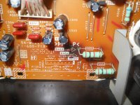
Long story short....I give a friend a Sony powered sub and he connects it to an amplified sub out. Poof! I took pics of the burn spot on the PCB and would like to replace the (diodes?) if possible but I don't know what values they are or what they are for that matter. I know that something else might have fried but if I'd start anywhere...it would but at the most obvious place. Can anyone help? Thanks.
Attachments
With all the electroltyic caps around, these might be voltage regulator zener diodes, in the 500 mw size. You would have to draw the circuit out to figure what values they are supposed to be. Although frequently zeners in this size say xZy where x is the voltage before the decimal point and y is the voltage after the decimal point. Look at the BZX79 series for example on datasheetcatalog.com.
The most common little brown diode, for non-voltage regulation, is the 1n4148, also usually marked. You need reading glasses and a light to see it.
You might be able to find the schematic diagram for your amplifier by speaker number on eserviceinfo.com, or perhaps, google.
The most common little brown diode, for non-voltage regulation, is the 1n4148, also usually marked. You need reading glasses and a light to see it.
You might be able to find the schematic diagram for your amplifier by speaker number on eserviceinfo.com, or perhaps, google.
You know, that burn or discolouration could well be normal. It looks nothing out of the ordinary tbh on a paxolin PCB with high wattage (as in they get hot !) metal oxide resistors nearby.
Two resistors, two zeners ? maybe the reference voltage for some rails.
Measure the voltage across the diodes first and see if they are some reasonable value.
Your first sentence can read in two ways... did the speaker output of this thing get connected to the speaker output of something else ? or did you just connect an amplified feed into the input of this Sony. If the first then look more toward the output stages for a fault.
Your first sentence can read in two ways... did the speaker output of this thing get connected to the speaker output of something else ? or did you just connect an amplified feed into the input of this Sony. If the first then look more toward the output stages for a fault.
Sorry. Yes...an amplified feed was fed to the sony amp'd sub.
Model #SA-WMSP1 50 watt.
Those are MTZJ15B 15Volt 500 mW Zener diodes which regulate voltage to the op-amps used in the subwoofer and along with those two 1K fusible resistors apparently fail often. Use the same type of resistor if replacing, to maintain fire safety.
Any Zener of the same voltage and equal or higher power should be fine. 1N965, NTE5024A, and BZX55C15 are similar inexpensive diodes. If it were me a 1 Watt type would be tempting for better reliability, soldering to the other side of the board if the wires are too thick for the holes.
Each diode should have that voltage in that ballpark across them in normal operation. Failure of a filter cap sometimes causes the diodes/resistors to fail. If that is the case your friend may have heard a loud hum just as the speaker died.
Checking diode resistance with power off, they should show low one direction and high the other just iike ordinary diodes using a suitable resistance scale on a multimeter (often identified with a diode symbol on digital meters). The two diodes should give similar readings. They normally get pretty warm, so the discoloration is common even when they are good. But failure is common. They're feed power from those two 1K Ohm resistors which are made to act like fuses, so they should be checked also.
That subwoofer has both line level and speaker level inputs, so your friend probably didn't blow it up.
In the future remember to include model numbers and any link to service info you might have when asking for help. It was only after some time pondering the possibilities that I happened to search for what turned out to be the model number, the SA-WM20 on the circuit board picture, and got lucky.
A free pdf of the service manual was downloadable without registration here (search site again if link fails, not sure if it changes):
SONY SONY SA-WM20 ACTIVE SUBWOOFER. Service Manual free download,schematics,datasheets,eeprom bins,pcb,repair info for test equipment and electronics
Thank You so much. And again, sorry for not first including the model number.I really appreciate the help. When I get the chance to replace the parts I'll post the outcome!
Just measure the voltage across each diode and post the result
I just had this same thing happen with the same sub after someone fed an amplified signal into it. I replaced the zeners (obvious discoloration) and checked the resistors, but am still getting a barely-there crackle (maybe some rumble) when a line level signal is fed into it and the level cranked on the sub. I just popped the board back out and put a meter on both zeners and got "OL" and 1m resistance on each of them respectively. Any thoughts on what I need to do next to revive this beast? Thanks in advance. -LBJ
What is the voltage across the zeners. These derive the two main rails for the signal stages.
You should have -/+15 volts on pins 4 and 8 of the opamps.
The DC voltage on pins 1 and 7 of the opamps (the output pins) should be zero. Check them !
See what all that shows first.
This "feeding an amplified signal into it" scenario should not damage the front end unless the voltage is many 10's of volts. To me, the most likely outcome is that the amp is overloaded so much that it blows the LM3886 power amp due to gross overloading and clipping.
So check very carefully the DC voltages on the LM3886. Be careful... one slip with the meter could cause damage.
Ok, checked the zeners and op amp pins and everything checks out. Assuming it's now the LM3886? I noticed some very helpful red lettering in the schematic in the service manual that tells me which pins should read what voltage. Quite helpful! Thanks for everything guys. Shall I now check against the voltages listed for the pins on the LM3886?
Sorry, not ignoring you, you hadn't posted enough yet to be out of moderation and so you hadn't triggered the thread notifier.
So the supplies across the zeners are OK and all supplies to the opamps are correct.
Can you confirm that is so ?
Also pins 1 and 7 of each opamp should be at zero volts DC.
If that is all OK then the LM3886 has to be suspect. Have you measured the supplies to it. Pins 1 and 5 should be around 40 volts DC and pin 4 around minus 40 volts. Output on pin 3 should be zero volts DC.
Edit... just another thought. Earlier you mention that there is distorted sound/crackling. Although the LM3886 is suspect it's worth checking the speaker too. Any DC fault could have damaged it. Speakers that have been abused can have the voice coil rubbing on the pole piece of the magnet.
Last edited:
Thanks Mooly. Sorry for the confusion. Yes, zeners are reading proper voltage as well as opamps on all counts. I will check the LM3886 and report back. I removed the speaker and hooked it up to my little 20watt amp and it sounds normal.
I was thinking about what could have caused this, and suspect that someone pulled the 1/8" jack out of their iPod while the receiver/amplifier was still on at significant volume, and being an amplified signal going to an active subwoofer (I know, not smart, but I didn't think my coworkers would be so negligent) this may have blown something? Am I explaining that clearly? Like when you pull a jack out of a guitar amp with it at full volume, that horrible split-second low-end pop with a tinge of ground hum?
Thanks for the help and advice. I really appreciate it. I'll check the LM3886 and get back to you.
- Status
- This old topic is closed. If you want to reopen this topic, contact a moderator using the "Report Post" button.
- Home
- Design & Build
- Parts
- Help identifying blown passive PCB components