Yes, Eva is the Member who I could not remember.Are you perhaps referring to Eva?
http://www.diyaudio.com/forums/power-supplies/76229-power-supply-decoupling.html
I see that excellent resource has been ruined by the loss of many of the pics.
Please attach pics. Don't leave them on remote servers.
Would a ferrite bead in series (with a film cap in parallel) be a better choice than a resistor? They are supposedly lossless at low frequencies, but provide a lossy inductance at HF through VHF frequencies. I am sure that modern opamps require some re-thinking of power supply decoupling, since "audio" opamps often have gain-bandwidth products into the VHF range.. . . When you want damping, the best option is to add it explicitly, with a small series resistor. And if, as a result the VHF decoupling properties become insufficient, you then add a small additional parallel capacitor . . .
Dale
Honestly, I didn't test this possibility thus I cannot tell for sure what would be the result.Would a ferrite bead in series (with a film cap in parallel) be a better choice than a resistor? They are supposedly lossless at low frequencies, but provide a lossy inductance at HF through VHF frequencies.
But I would be extremely cautious: in this kind of arrangement, the harmful resonance frequency would be much lower than the intended range of action of the bead, and the losses would be correspondingly small, leading to a heightened resonance at a lower frequency. Exactly the kind of thing you want to avoid.
I will try to test this configuration tomorrow, or later (remind me if I forget)
Yes and no: you certainly have to be more careful, but the issues are different, and most VHF/UHF circuits would misbehave badly if you applied even the best standards of AF decoupling: have you already seen a radar power circuit? You'll see what I mean.I am sure that modern opamps require some re-thinking of power supply decoupling, since "audio" opamps often have gain-bandwidth products into the VHF range.
In addition, most UHF circuits do not have to deal with subsonic frequencies, and are happy with a good, well placed 10nF as sole decoupling.
there is a range of combination smd CRC, CLC, CRCRCRC network parts by murata that I would like to employ, but without a scope to test effectiveness its pot luck. i will rectify this soon, but in the meantime i wonder if anyone has used these parts here? i know that iancanada has used them to effect in his fifo project see parts c4, c9 which are murata NF series EMIFIL and he has also used one of the CLC parts above them. they have a whole range targeted at power line (up to 10A parts), data line and signal line frequencies that perhaps deserves some further investigation for decoupling while keeping resonance damping in mind.


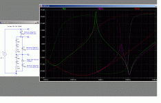
I have tested the proposition in sim. Since LTspice has excellent models of actual ferrite beads and capacitors, the results are as good as the reality.Would a ferrite bead in series (with a film cap in parallel) be a better choice than a resistor? They are supposedly lossless at low frequencies, but provide a lossy inductance at HF through VHF frequencies. I am sure that modern opamps require some re-thinking of power supply decoupling, since "audio" opamps often have gain-bandwidth products into the VHF range.
Dale
The model of the cap didn't include series inductance though, I added 6nH which is reasonable for such a size.
The simulation doesn't take into account any supplementary track inductance, this mimics the best possible practice, where the two caps are physically superposed.
Any real situation could only be worse.
The red curve is for the electrolytic alone.
The magenta is for the 100n and 100µ simply paralleled, causing the familiar parallel-series resonances pair.
The green is with the ferrite bead added to the electrolytic. As I suspected, the effect is rather catastrophic.
Attachments
A similar discussion is going on in the Signal Integrity, digital design world regarding fetrrites:
Printed Circuit Design & Fab Magazine Online
http://www.ipblox.com/pubs/DesignCon_2011/11-TA3Paper_Weir_color.pdf
http://www.ipblox.com/pubs/DesignCon_2011/11-TA3Slides_Weir_as_presented.pdf
I have seen so many different schemes involved as ALL electronics engineers have their own favorite scheme.
Printed Circuit Design & Fab Magazine Online
http://www.ipblox.com/pubs/DesignCon_2011/11-TA3Paper_Weir_color.pdf
http://www.ipblox.com/pubs/DesignCon_2011/11-TA3Slides_Weir_as_presented.pdf
I have seen so many different schemes involved as ALL electronics engineers have their own favorite scheme.
I have tested the proposition in sim. Since LTspice has excellent models of actual ferrite beads and capacitors, the results are as good as the reality.
The model of the cap didn't include series inductance though, I added 6nH which is reasonable for such a size.
The simulation doesn't take into account any supplementary track inductance, this mimics the best possible practice, where the two caps are physically superposed.
Any real situation could only be worse.
The red curve is for the electrolytic alone.
The magenta is for the 100n and 100µ simply paralleled, causing the familiar parallel-series resonances pair.
The green is with the ferrite bead added to the electrolytic. As I suspected, the effect is rather catastrophic.
there are ferrite beads and ferrite beads, was any effort made to choose or tune the value of the bead used to the particular cap? just curious, as just like bypass caps surely just throwing one on there without thought of matching it to the application and the other parts in parallel is bound to cause sub-par results. i'm not defending the use of ferrites in analogue audio, i've only just started investigating it, so dont have an opinion; but i doubt that murata would produce a specialised range for signal lines if they produced such horrible results consistently.
They produce horrible results because they are not meant to be used that way: normally, they are used as "RF scissors" to cut the propagation of unwanted RF signals, typically (but not exclusively) as a part of a second order lowpass filter.there are ferrite beads and ferrite beads, was any effort made to choose or tune the value of the bead used to the particular cap? just curious, as just like bypass caps surely just throwing one on there without thought of matching it to the application and the other parts in parallel is bound to cause sub-par results. i'm not defending the use of ferrites in analogue audio, i've only just started investigating it, so dont have an opinion; but i doubt that murata would produce a specialised range for signal lines if they produced such horrible results consistently.
Here, when placed in series with the capacitor, their damping properties are totally insufficient to produce the desired effect (if there is such a thing).
Other beads would yield similar results, with the resonance peak higher or lower, and the resonance frequency shifted higher or lower.
The optimum combination would be minimal inductance and maximal resistance, ie a pure resistance.
Out in the murky world of electronics you see every combination of caps and ferrites when doing PCB's, a lot of engineers have their own unshakable beliefs regarding this, the most extreme case was a cap, ferrite, cap on EVERY power pin of a digital board!!!!!
from that through various combinations; to my favorite and the quietest for digital (but also analogue rf suppressions) is planar capacitance (from very closely spaced power and ground planes, <0.05mm dielectric) with minimal decoupling capacitors...
from that through various combinations; to my favorite and the quietest for digital (but also analogue rf suppressions) is planar capacitance (from very closely spaced power and ground planes, <0.05mm dielectric) with minimal decoupling capacitors...
- Status
- This old topic is closed. If you want to reopen this topic, contact a moderator using the "Report Post" button.
- Home
- Design & Build
- Parts
- Small 5mm 0.1uF caps - what's best?
