Horrors, I just found out that my favorite mute transistor, the Toshiba 2SC3326 is no longer available. In fact, it has been my favorite so long, that I don't remember using any other. So, what are you using, any that you find particularly good?
Good:
-low resistance => good attenuation, the whole point
-transparent sound (On the other hand, I would think most are when used to short the signal to ground, not putting signal through the device)
-available
-cheap(ish)
-relatively robust against ESD
Thank you for pointers!
Good:
-low resistance => good attenuation, the whole point
-transparent sound (On the other hand, I would think most are when used to short the signal to ground, not putting signal through the device)
-available
-cheap(ish)
-relatively robust against ESD
Thank you for pointers!
Have you considered using FET's instead of bjt transistors ?
http://www.diyaudio.com/forums/digi...ication-eliminate-distortion.html#post2254391
http://www.diyaudio.com/forums/digi...ication-eliminate-distortion.html#post2254391
Would BF862 from NXP make a good muting transistor ?
http://www.nxp.com/documents/data_sheet/BF862.pdf
http://www.nxp.com/documents/data_sheet/BF862.pdf
Would BF862 from NXP make a good muting transistor ?
http://www.nxp.com/documents/data_sheet/BF862.pdf
Quite possibly yes...
Vgs OFF MIN is -0.3V, so the gate voltage would have to be arranged to closely track the source when ON
I'm no expert, but please help me understand.
In a muting circuit the Source would be connected to ground while the drain would be connected to the signal line.
With zero volt present at the gate, the transistor would "pull" to ground.
With a few volt of negative voltage at the gate the transistor would be open.
How can you track the source then ?
For output muting relays are the best choice. However there are a few CD-players that use a fast muting when track changes occurs, such as skipping, pausing etc. In this case relays are just too slow to react.
Another application is a soft muting circuit after the input selector relays in my pre-amp. Although i use NEC relays with low switching noise, sometimes you can still hear a mild pop. Using a transistor muting circuit after the relays prevents this behavior.
Another application is a soft muting circuit after the input selector relays in my pre-amp. Although i use NEC relays with low switching noise, sometimes you can still hear a mild pop. Using a transistor muting circuit after the relays prevents this behavior.
This problem is far from uninteresting.
First of all, it is crucial to control properly the mute transistor; many things could go wrong at this stage.
But when properly controlled, a simple transistor can outperform many costlier options.
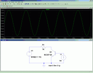
Here is an example based on the BC337, a european all-purpose transistor.
With a control current equal to the max peak signal current, the resistance is a shade under 4Ω, and has a good linearity, if the sim is to be believed.
Which could be verified very easily.
In the off state, the capacitance at 0V is ~=15pF. It would be even less with a reasonable negative bias, say -5V.
Compared to optocouplers, this is significantly better: even at 50V, the capacitance is higher, ~25pF, and unlike the transistor, negative bias cannot be applied without interfering with the signal.
Since the semiconductor capacitance is non-linear, it will be the main source of distortion in the inactive (signal on) state.
First of all, it is crucial to control properly the mute transistor; many things could go wrong at this stage.
But when properly controlled, a simple transistor can outperform many costlier options.
Here is an example based on the BC337, a european all-purpose transistor.
With a control current equal to the max peak signal current, the resistance is a shade under 4Ω, and has a good linearity, if the sim is to be believed.
Which could be verified very easily.
In the off state, the capacitance at 0V is ~=15pF. It would be even less with a reasonable negative bias, say -5V.
Compared to optocouplers, this is significantly better: even at 50V, the capacitance is higher, ~25pF, and unlike the transistor, negative bias cannot be applied without interfering with the signal.
Since the semiconductor capacitance is non-linear, it will be the main source of distortion in the inactive (signal on) state.
Attachments
Hi Mooley,
Fets are okay, but relays are a better idea. That's only my point of view though.
Hi JuKu,
Any BJT transistor used for this must have a high reverse base emitter breakdown voltage. These are special parts designed for this use. Another popular one is 2SC2878. Again, these are not normal transistors and a part like a BC337 will misbehave unless specific measures are taken to avoid the problem. Note that the accepted reverse breakdown voltage, emitter-base, is about 5 ~ 7 VDC.
Why do I prefer a relay? Charge injection. You can sometimes hear the mute signal a bit. A lot if the part is defective. As for complete attenuation, that isn't required. All you need to accomplish is to reduce noise in the audio path to non-dangerous levels, or something less than annoying to the user.
This isn't about absolutes. This entire question revolves around achieving a mute to levels below some acceptable level. A relay shorting the output to signal common would be the best choice as far as I'm concerned. Understand that a relay may create a click or pop noise as well.
Another solution is to use an analog switch. A 4066 is one example, and a 4966 is the high voltage version (same pinout). Then there are analog switches made by other companies that incorporate a muting rate that avoids thumps. These are generally better than the old 4066 (4052, 4053 ... ) type ideas.
-Chris
The problem is not the capacitance in itself, but the fact it is non-linear.High end sony players use a little inductance (6-10u) in serie apparently to compensate for the capacitance.
I don't have the experience to comment on it's merrits.
Peaking it with a coil would only be useful in the MHz region, and it would exacerbate the non-linearity problem.
It is not very often you have to process voltages >5V at a signal level.Again, these are not normal transistors and a part like a BC337 will misbehave unless specific measures are taken to avoid the problem. Note that the accepted reverse breakdown voltage, emitter-base, is about 5 ~ 7 VDC.
Hi davidsrsb,
Hi Elvee,
Try it - please.
-Chris
Absolutely!5V is a bit low for comfort, I have seen crazy CD players with 5V output and just about anything is possible from a valve phono preamp.
Hi Elvee,
Enough of them have gone defective with the higher E-B rating to seriously challenge that line of reasoning. In fact, using a normal transistor in place of a special muting type always fails to work properly. At least in anything I've seen to date.It is not very often you have to process voltages >5V at a signal level.
Try it - please.
-Chris
- Status
- This old topic is closed. If you want to reopen this topic, contact a moderator using the "Report Post" button.
- Home
- Design & Build
- Parts
- Mute transistor choices?