I'm looking to accept either 9v or 48v on the input side, and put out a clean say, 5v on the output side to drive a couple of leds.
I think the gizmo I need is a "linear voltage regulator".
The application is a stomp box that can run on with a 9v battery, or phantom power.
thanks
I think the gizmo I need is a "linear voltage regulator".
The application is a stomp box that can run on with a 9v battery, or phantom power.
thanks
Is that all you want to do, run a few leds ? It's important because that determines how much current is required and consequently the power dissipated in the reg. Also 50 volts (approx) is more than a normal 3 pin reg IC can handle.
If it's just LED's a constant current diode could be a possiblity. 9V or 50v input and the LED's would be same brightness.
If it's just LED's a constant current diode could be a possiblity. 9V or 50v input and the LED's would be same brightness.
It this point it would only need to supply 1 indicator led and one photo-mosfet.
The only modification I foresee is perhaps adding a timer to make the led flash instead of constant on... just to make it a bit more ... "HEY, IM ON MAN!!!"
I'm open to any solution that works. The constant current diode sounds like it maintains the current supply at a specified level, but what about voltage? I don't think leds will like a voltage that changes.
I read through this thread
SparkFun Electronics • View topic - Constant Current Diodes
And found ome more words to learn about, but I'm still not sure what I need to allow for selecting to power my unit via phantom power or 9v battery.
thanks for your help
Supplying an LED is easy. One constant current diode and one or more LED in series.
If you are running other stuff of the supply (photo-mosfet !! what's that ?) then you probably need a reg of some sort.
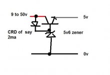
Discrete component design, one transistor, one zener and perhaps again a current diode for bias. In outline this is all you need.
Edit... not sure of the official symbol for a CRD")
If you are running other stuff of the supply (photo-mosfet !! what's that ?) then you probably need a reg of some sort.
Discrete component design, one transistor, one zener and perhaps again a current diode for bias. In outline this is all you need.
Edit... not sure of the official symbol for a CRD
Attachments
Thank you Mooly.
Is a CRD a constant current diode?
Is the transistor a BJT, or some other flavor?
Your sketch made this alot easier, but I want to make sure I understand it. Is this right?
EDIT: the crd is supposed to say 2ma.

The photo-mosfet is just an led, but it is inside a chip with a photo sensitive transistor that acts as a switch. when the led goes on, the transistor closes.
Is a CRD a constant current diode?
Is the transistor a BJT, or some other flavor?
Your sketch made this alot easier, but I want to make sure I understand it. Is this right?
EDIT: the crd is supposed to say 2ma.
The photo-mosfet is just an led, but it is inside a chip with a photo sensitive transistor that acts as a switch. when the led goes on, the transistor closes.
Last edited:
Yes, CRD is a constant current diode or "current regulating diode". 2 milliamps or thereabouts. It would be the E202 device here.
Browse for Products | CPC
If we didn't use a CRD or similar and used just a resistor instead, then the base current available to the transistor would vary wildly depending on whether you used 9 volts or 48 volts.
Browse for Products | CPC
If we didn't use a CRD or similar and used just a resistor instead, then the base current available to the transistor would vary wildly depending on whether you used 9 volts or 48 volts.
I've added this section to my main schematic. I have a few final questions, if you can humor me.
The zener is...5.6 volts.
what type is the transistor, from your diagram I'd guess BJT.
How stable is the output from this circuit section? as stable as a voltage regulator chip?
I don't have a need for it right now, but if I were to want to power a microchip from this, would it work ok?
Thanks, I'm new to all this, and I appreciate your time.
The zener is 5.6 volts because the volt drop across the base emitter junction of the transistor will reduce that to nearer 5v.
Is it as stable as reg... no, but it's good. It lacks "feedback" to maintain the output absolutely constant. The more current you draw and the lower (slightly) the output becomes. No problem supplying a PIC (if that's what you mean by microchip) from this as long as the current drawn is not too high.
A normal reg is no good as it has to handle nearly 50 volts input... but... depending on how complex you wanted to make this then using a different switching arrangement could allow a 5v reg for use with 9 volts and switch a "pre reg" in on 48 volts to drop the 48v to say 12 and then feed that to the reg.
The transistor wants to be a device like a BD139,
STMICROELECTRONICS|BD139|TRANSISTOR, NPN, TO-126 | CPC
Remember heat is the big problem with any series reg like this (and that includes IC regulators) 48v in and 5 volt out means the series pass element (the transistor) is dropping 43 volts. Even at 100ma load thats 4.3 watts... too much for a transistor not on a heatsink.
Thanks for the extra info. I'm trying to wrap my head around what is going on in the circuit.
It looks to me like the voltage input (48 or 9 volts) runs straight through the transistor and out to the load. Meanwhile a portion of the input is routed through the CRD to change how much current the transistor allows to flow from source to load. The zener shunts all excess power to ground.
So this whole assembly sort of acts like a variable voltage divider? Automatically splitting the input between the load and ground?
I've been looking up all the info I can about diodes online, but I'm still not quite to the point of understanding it.
As for the more complicated option, I already have a switch in the circuit to decide whether it is powered from 9v battery or 48v phantom power. So it would be pretty easy, I think, to drop the 48 v to some smaller voltage using a resistor. The point being, this device will only be attached to one or the other power source at a time.
The only thing that matters is that the load can be designed to use only one voltage (like 5v) even if the ultimate source of power is 9v or 48v.
As long as a pic/avr can run off the output...that's all the stability I'd need, even in the most advanced version of my design. But, I'm interested in learning more about power regulation...do you have any good links that talk about using "feedback" to stabilize current?
thanks again.
It works like this...
The zener diode always develops around 5.6 volts across it when fed with a current of a few tenths of a milliamp up to a few 10's of milliamps. The power rating of the zener determines the upper current limit. The "resistance" feeding the zener determines this current. It can be a resisor or a CRD.
So far so good.
What we do now is apply that fixed 5.6 volts to the base of transistor. The transistor base voltage is now fixed (at 5.6 volts). The collector goes to the unregulated positive supply (9 to 50 volts). The emitter is constant at around 5 volts (Vbase minus the base emitter volt drop... the B-E junction behaves like a diode dropping around 0.6 to 0.7 volts).
The transistor allow for the current fed "into" the base to be amplified and thus the transistor can supply a reasonable current into the load.
If you were to build this for real then it should include a small cap across the zener (say a 0.1uf) and a small electrolytic cap across the 5 volt rail.
The CRD is not not like a diode at all... they just call them that.
Have to see if I can find any links on simple discrete voltage regulators.
I think tbh something like this would best,
http://www.amazon.co.uk/Art-Electro...0957/ref=sr_1_1?ie=UTF8&qid=1315246681&sr=8-1
It's a classic text and very comprehensive. You need to understand all the basics first really.
http://www.amazon.co.uk/Art-Electro...0957/ref=sr_1_1?ie=UTF8&qid=1315246681&sr=8-1
It's a classic text and very comprehensive. You need to understand all the basics first really.
- Status
- This old topic is closed. If you want to reopen this topic, contact a moderator using the "Report Post" button.
- Home
- Design & Build
- Parts
- 48v - 9v linear voltage regulator recommendation?