Hi everyone,
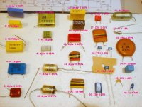
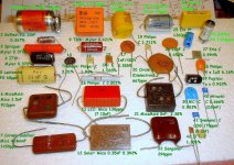
I want to measurement some film and electrolytic capacitors by an Agilent 4284 LCD meter. Cap to be measured are general part as well as expensive audio grade. The measured data will show us whether those $$$ caps are really better technically.
Firstly, capacitance and dissipation factor will be measured at certain freq, e.g. 1 kHz. We can use this factor to get the ESR. Please see the attached doc.
Is it an interesting project? Please comment.
Attachments
I think it is interesting: I had begun some times ago, but I think the files are not accessible anymore.
Here they are.
Conrad had also made some interesting measurements in this field.
Hopefully, this post will become a reference library.
This too might be of interest:
http://www.diyaudio.com/forums/powe...lm-caps-electrolytic-caps-17.html#post2257381
Good work!
Here they are.
Conrad had also made some interesting measurements in this field.
Hopefully, this post will become a reference library.
This too might be of interest:
http://www.diyaudio.com/forums/powe...lm-caps-electrolytic-caps-17.html#post2257381
Good work!
Attachments
Getting D is a good start but won't tell you much about audio performance. It will let you take a good guess at unknown film materials. I don't know the frequency range of the 4284, but some curves up to 1MHz would be interesting if you can keep the lead lengths short- even half an inch will interfere with the measurements. Distortion is more useful. You should be able to clearly see how bad a polyester is, compared to almost any other film. You should also be able to see that some of the high end expensive audio caps don't appear to offer anything more than moderately priced Digikey caps!
I should go back and do some more measurements- stuff I've measured.
I should go back and do some more measurements- stuff I've measured.
Interesting measurements. I was puzzled by your remark that 3rd harmonic residual is "counter intuitive" - that is exactly what I would expect from an unbiased cap. You can't get 2nd harmonic unless something tells the cap which end is which - DC bias or dielectric poling for example.
Getting D is a good start but won't tell you much about audio performance. It will let you take a good guess at unknown film materials. I don't know the frequency range of the 4284, but some curves up to 1MHz would be interesting if you can keep the lead lengths short- even half an inch will interfere with the measurements. Distortion is more useful. You should be able to clearly see how bad a polyester is, compared to almost any other film. You should also be able to see that some of the high end expensive audio caps don't appear to offer anything more than moderately priced Digikey caps!
I should go back and do some more measurements- stuff I've measured.
Hi Conrad,
Thank you for your input. The freq range of 4284 is 20 Hz to 1 MHz.
 The main problem is the fear that I may be getting a little dimmer every day.
I would like to present the data obtained today, though this is not following the planned sequence.
Most people parallel a film cap to an AC coupling/DC blocking e-cap. This is said to lower the impedance and to offset the adverse effect of e-cap such that sound quality is improved. Some people even replace the e-cap with a very expensive film cap of similar capacitance.
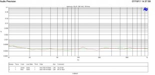
I measured the THD of a low-pass filter formed by a capacitor and a 1k metal film resistor. Driving signal amplitude is 10 Vrms. The test setup is taken from Self's small signal book.
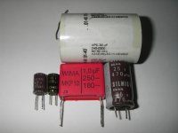
A Nippon Chemi-Con KZE series 47 uF, 63 V is used in the first test. The non-linear effect of e-cap is shown by the increased THD in low freq. Shall we add film cap to in parallel with the e-cap. A WIMA 1 uF film cap is employed. However, it does not offer any improvement.
In second test, a 30 uF film cap (mostly like a polyester one) alone is tested. It is effectively distortion free. However, it has a very big axial case.
Two 470 uF caps are used in the third test. One is an inexpensive KZJ series and the other is top-end audio grade SILMIC II. Both of them are effectively identical and distortion free. The SILMIC is more than 30 times the cost of the KZJ. Is it worth?
Dissipation factor (at 120 Hz):
47uF, KZE: 0.018
30uF film: 0.00087
470uF, KZJ: 0.031
470uF SIMLIC II: 0.029
Most people parallel a film cap to an AC coupling/DC blocking e-cap. This is said to lower the impedance and to offset the adverse effect of e-cap such that sound quality is improved. Some people even replace the e-cap with a very expensive film cap of similar capacitance.
I measured the THD of a low-pass filter formed by a capacitor and a 1k metal film resistor. Driving signal amplitude is 10 Vrms. The test setup is taken from Self's small signal book.
A Nippon Chemi-Con KZE series 47 uF, 63 V is used in the first test. The non-linear effect of e-cap is shown by the increased THD in low freq. Shall we add film cap to in parallel with the e-cap. A WIMA 1 uF film cap is employed. However, it does not offer any improvement.
In second test, a 30 uF film cap (mostly like a polyester one) alone is tested. It is effectively distortion free. However, it has a very big axial case.
Two 470 uF caps are used in the third test. One is an inexpensive KZJ series and the other is top-end audio grade SILMIC II. Both of them are effectively identical and distortion free. The SILMIC is more than 30 times the cost of the KZJ. Is it worth?
Dissipation factor (at 120 Hz):
47uF, KZE: 0.018
30uF film: 0.00087
470uF, KZJ: 0.031
470uF SIMLIC II: 0.029
Attachments
Adding a parallel film cap will not affect LF distortion, as you have found. If it has any effect at all, it will be to modify HF impedance (for better or worse).
A capacitor will only add distortion if it has some signal voltage across it. This will depend on cap value, circuit impedance and signal frequency. For 47uF the distortion begins to rise out of the analyser floor at about 70Hz. Other things being equal, I would expect 470uF to do this around 7Hz. The analyser has a small rise around here anyway so it might not be able to test larger electrolytics.
What you have demonstrated is that electrolytics are fine, provided they have little or no signal voltage across them. This means that electrolytic caps should not determine the LF point of an amplifier, unless this is significantly below the LF limit of the input signal. Alternatively, use a normal cap early on to set the LF point.
Yep, paralleling film caps offers little benefit, especially if you have any lead length in the system. I don't talk about it much because everybody likes to do it and "knows" it must be better. Just for fun, run a curve or two up to a MHz and compare some nice little cap with the same cap and a few inches of extra lead length. Those who haven't seen it will be amazed.
Yep, paralleling film caps offers little benefit, especially if you have any lead length in the system. I don't talk about it much because everybody likes to do it and "knows" it must be better. Just for fun, run a curve or two up to a MHz and compare some nice little cap with the same cap and a few inches of extra lead length. Those who haven't seen it will be amazed.
I agree with your point in applications like power supply. On the other hand, lead length is not an issue in audio band signal path DC blocking. I think this is non-sense to parallel a film cap to a DC blocking e-cap. This is mostly said to reduce HF impedance. The freq of interest is 20 Hz to 20 kHz. In this range, commonly used e-cap most likely have lower impedance than a film cap. Unless the film cap is a large one, e.g. > 10 uF.
The e-cap in NFB of Class-AB amp may need further thinking. Output signal contains high order harmonics. e-cap HF characteristic (beyond its resonant freq) might be important.
Last edited:
Some time ago I was thinking about what it would take to get really low impedance over the full audio range. It turns out the only way I could imagine was to use very large film caps, with high quality motor caps being the most sensible. Paralleling electros with small film caps didn't help because the impedance of small values is high, regardless of esr, so you just end up with the impedance of the electrolytic. Low impedance at high frequencies is easy. Low impedance at low frequencies is best done via active circuits.
It would be helpful if you added more information on your test like which Audio Precision you used, the settings (e.g. output impedance of the AP generator, balanced/unbalanced, analyzer BW, sweep frequency steps, etc.).. If your AP has the DSP option, plot the FFT at different discrete frequencies in order to differentiate the noise from the harmonics. It doesn't make a lot of sense to limit your THD+N plots to 1kHz when the AP can go much higher. You need to be more detailed with your tests. That's what I'm trying to get at.
Aluminum electrolytics behave differently when DC bias is applied which they do encounter a lot when used for AC coupling and bypass.
Aluminum electrolytics behave differently when DC bias is applied which they do encounter a lot when used for AC coupling and bypass.
Most people parallel a film cap to an AC coupling/DC blocking e-cap. This is said to lower the impedance and to offset the adverse effect of e-cap such that sound quality is improved. Some people even replace the e-cap with a very expensive film cap of similar capacitance.
I measured the THD of a low-pass filter formed by a capacitor and a 1k metal film resistor. Driving signal amplitude is 10 Vrms. The test setup is taken from Self's small signal book.
A Nippon Chemi-Con KZE series 47 uF, 63 V is used in the first test. The non-linear effect of e-cap is shown by the increased THD in low freq. Shall we add film cap to in parallel with the e-cap. A WIMA 1 uF film cap is employed. However, it does not offer any improvement.
In second test, a 30 uF film cap (mostly like a polyester one) alone is tested. It is effectively distortion free. However, it has a very big axial case.
Two 470 uF caps are used in the third test. One is an inexpensive KZJ series and the other is top-end audio grade SILMIC II. Both of them are effectively identical and distortion free. The SILMIC is more than 30 times the cost of the KZJ. Is it worth?
Last edited:
Thank you for your advice.
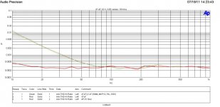
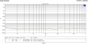
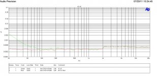
The AP is System One Dual Domain. You can visit AP High Performance Audio Analyzer & Audio Test Instruments : Downloads to download its full spec. In my test, the output impedance is 50 Ohms. Balanced connection is used. The upper audio bandwidth for THD sweep is set to 22 kHz. For the e-cap THD sweep, we can go to 20 kHz and beyond. However, the e-cap is effectively short circuit, distortionless when freq is above 500 Hz as shown in the figure below.
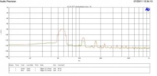
FFT (Avg = 16) for 57 Hz is shown in the next figure. The 47 uF DUT generates measurable second and third harmonics.
I will apply DC bias in coming tests.
The AP is System One Dual Domain. You can visit AP High Performance Audio Analyzer & Audio Test Instruments : Downloads to download its full spec. In my test, the output impedance is 50 Ohms. Balanced connection is used. The upper audio bandwidth for THD sweep is set to 22 kHz. For the e-cap THD sweep, we can go to 20 kHz and beyond. However, the e-cap is effectively short circuit, distortionless when freq is above 500 Hz as shown in the figure below.
FFT (Avg = 16) for 57 Hz is shown in the next figure. The 47 uF DUT generates measurable second and third harmonics.
I will apply DC bias in coming tests.
Attachments
Thanks for the link but I'm quite familiar with the AP System. I've used several versions before for years.
AP's strength is on its FFT and multitone feature. Learn how to use it instead of the same old single tone and THD+N routine.
AP's strength is on its FFT and multitone feature. Learn how to use it instead of the same old single tone and THD+N routine.
Thank you for your advice.
The AP is System One Dual Domain. You can visit AP High Performance Audio Analyzer & Audio Test Instruments : Downloads to download its full spec.
I will apply DC bias in coming tests.
AP's strength is on its FFT and multitone feature. Learn how to use it instead of the same old single tone and THD+N routine.
Sounds like a good idea. Will look into this. Thank you.
Real good information
so let me ask if im correct...if I take and ADD 10x to the input cap in my amplifier the low freq will reduce THD TIM?
I wanted to re-post this information as IMO think its very important...
most amplifiers i see built on Diy forum use not enough for lowest distortion!
Lawrence
so let me ask if im correct...if I take and ADD 10x to the input cap in my amplifier the low freq will reduce THD TIM?
I wanted to re-post this information as IMO think its very important...
most amplifiers i see built on Diy forum use not enough for lowest distortion!
Lawrence
If the input coupling cap is too small and electrolytic (or other nonlinear dielectric) then this can cause a small amount of LF distortion. This is well known.
The general advice is to ensure that any electrolytics are not setting the LF rolloff, and themselves set rolloffs at least 10x below the main LF rolloff. Provided this is done (and it usually is) there would seem to be no advantage in making the input cap any bigger.
The general advice is to ensure that any electrolytics are not setting the LF rolloff, and themselves set rolloffs at least 10x below the main LF rolloff. Provided this is done (and it usually is) there would seem to be no advantage in making the input cap any bigger.
- Status
- This old topic is closed. If you want to reopen this topic, contact a moderator using the "Report Post" button.
- Home
- Design & Build
- Parts
- Capacitor measurement