Hi,
I am designing a high-voltage amplifier to directly drive ESLs. I'm not ready to disclose the design yet, but I DO need a power transformer with a large isolation between primary and secondary, at least 3kV peak, as well as very low capacitance between the primary and secondary.
I've got a quote by one manufacturer which specs 250pF between prim and sec which is too much. I want to get (far) below 100pF.
I need about 20W power, 115/230V prim. Sec voltage should be 6V nominal.
I *think* I might need to wind my own, like on a C-core with physically separated primary and secondary. Anyone knows where I could buy kits of cores and bobbins or any other solution?
thanks,
jan didden
I suppose your circuit swings the power supply secondary with audio voltage and therefore needs low capacitcance to primary? The best way to drop capacitance is to increase the transformer frequency, which makes all parts of the transformer smaller.
Maybe include a switching power supply with your amp? Or maybe HF linear.
Maybe include a switching power supply with your amp? Or maybe HF linear.
Last edited:
I suppose your circuit swings the power supply secondary with audio voltage and therefore needs low capacitcance to primary? The best way to drop capacitance is to increase the transformer frequency, which makes all parts of the transformer smaller.
Maybe include a switching power supply with your amp? Or maybe HF linear.
Yes. I did that for the screen supply of the upper tube (those CCFL transformers are great & cheap!). But I also need a solution for the heater (6V @ 2.7A). I'm hesitating to go the DC-DC converter route as I'm not familiar in that field and I want to build an audio amp not embarking on a new field of study.
")
What do you mean by 'hf linear'?
jan didden
For "HF linear" I meant sine drive to the transformer primary as from something like a class AB power amplfier. Probably too complicated to be worthwhile. I mean it would be easy enough to wire up but a lot of circuitry for the job.
Maybe for only 20 watts you could make a 60Hz cut core or any dual bobbin (as in one bobbin on either side of the core) arrangement work for less than 100p parasitic. I'd figure you'd want to select a bobbin for the secondary that will get you a square winding cross section (to minimize overall winding surface area, and therefore parasitic capacitance) while allowing for quite a bit of insulation/distance to the core. A full shield can drop the overall pri-sec coupling capacitance but of course it doesn't drop the capacitance from secondary to shield.
Maybe for only 20 watts you could make a 60Hz cut core or any dual bobbin (as in one bobbin on either side of the core) arrangement work for less than 100p parasitic. I'd figure you'd want to select a bobbin for the secondary that will get you a square winding cross section (to minimize overall winding surface area, and therefore parasitic capacitance) while allowing for quite a bit of insulation/distance to the core. A full shield can drop the overall pri-sec coupling capacitance but of course it doesn't drop the capacitance from secondary to shield.
lowest pri-sec C in standard xfmrs comes from physical separation of the windings - "worldtrans" international accepted double reinforced insulation mains transformers with split bobbin construction have 5-10x less parasitic coupling C than layer wound types (toroids are the worst)
dual bobbin "semi-toriodial" C, R core types are intermediate in coupling C since they still put pri, sec side by side in both bobbins to cut leakage
the double insulated mains xfmrs must pass 4KV hi-pot but may not be safe to operate at continuous 3KV - possibly chaining one (or more) similar construction, physical size 1:1 mains isolation xfmr in series would give you a acceptable hobbyist solution (add V equalizing R divider??)
I have measured few 10s of pF in the dual bobbin EI types - series connection can cut that by a factor of N
I'm not saying that would be "safe" - you decide
electrostatic shields are not helpful in this application - multiple shields can give impressively low in-out C numbers at the cost of high winding to shield C - so you have to have a lo Z "AC gnd" (or signal node in Jan's app) termination to "bootstrap away" the shield to sec C
Last edited:
I would say you would choose either a split bobbin or electrostatic shield. You can reach less than 10pF with a properly arranged shield between windings.
Well to be specific, I would need low C from the secondary to the rest of the world...
jan didden
For "HF linear" I meant sine drive to the transformer primary as from something like a class AB power amplfier. Probably too complicated to be worthwhile. I mean it would be easy enough to wire up but a lot of circuitry for the job.
Maybe for only 20 watts you could make a 60Hz cut core or any dual bobbin (as in one bobbin on either side of the core) arrangement work for less than 100p parasitic. I'd figure you'd want to select a bobbin for the secondary that will get you a square winding cross section (to minimize overall winding surface area, and therefore parasitic capacitance) while allowing for quite a bit of insulation/distance to the core. A full shield can drop the overall pri-sec coupling capacitance but of course it doesn't drop the capacitance from secondary to shield.
Yes that would work, at least if I can insulate the sec to at least 6kV peak. Are there any companies that sell this type of xformer cores and bobbins?
jan didden
lowest pri-sec C in standard xfmrs comes from physical separation of the windings - "worldtrans" international accepted double reinforced insulation mains transformers with split bobbin construction have 5-10x less parasitic coupling C than layer wound types (toroids are the worst)
dual bobbin "semi-toriodial" C, R core types are intermediate in coupling C since they still put pri, sec side by side in both bobbins to cut leakage
the double insulated mains xfmrs must pass 4KV hi-pot but may not be safe to operate at continuous 3KV - possibly chaining one (or more) similar construction, physical size 1:1 mains isolation xfmr in series would give you a acceptable hobbyist solution (add V equalizing R divider??)
I'm not saying that would be "safe" - you decide
electrostatic shields are not helpful in this application - multiple shields can give impressively low in-out C numbers at the cost of high winding to shield C - so you have to have a lo Z "AC gnd" (or signal node in Jan's app) termination to "bootstrap away" the shield to sec C
I just looked at isolation transformers from Coilcraft and Halo; some are spec'ed for 4kV RMS isolation which would be perfect. They are developed for DC-DC converter chips from TI or Maxim.
Now if I could find a ref design...
I guess this type of transformer would have low secondary capacitance? Not spec'ed as far as I could see.
Anybody has experience with diy dc-dc converters?
jcx you have a link to some of this 'worldtrans' stuff?
jan didden
Hi Jan,
I use c-cores exclusively for power transformers and all kinds of audio transformers, mainly for tube amplifiers.
Besides expertise in winding technology for electrostatic (high voltage) applications is nearby.
And that in your own country....maybe you drop me a note to see what can be done.
I use c-cores exclusively for power transformers and all kinds of audio transformers, mainly for tube amplifiers.
Besides expertise in winding technology for electrostatic (high voltage) applications is nearby.
And that in your own country....maybe you drop me a note to see what can be done.
Hi Jan,
I use c-cores exclusively for power transformers and all kinds of audio transformers, mainly for tube amplifiers.
Besides expertise in winding technology for electrostatic (high voltage) applications is nearby.
And that in your own country....maybe you drop me a note to see what can be done.
I will surely do that!
BTW In my own country, that's not exceptional. Some of the best minds migrate here
, what with our 'coffee shops' and all.jan didden
What do you mean by 'hf linear'?
jan didden
Using sine converters, you can easily go down to single digit pF figures without really trying hard: complexity can truly be minimal, as you can see below:
Attachments
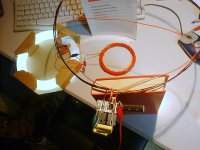
Using sine converters, you can easily go down to single digit pF figures without really trying hard: complexity can truly be minimal, as you can see below:
Sine converters as such doesn't seem a problem; just a bunch of chip amps to drive xformers. BUT, 5600V isolation? How would you do that? At 20W?
jan didden
Well, what price tag is acceptable to you - there is a lot of power supplies for EBW, to power cathode.Hi,
I am designing a high-voltage amplifier to directly drive ESLs.
Anyone knows where I could buy kits of cores and bobbins or any other solution?
thanks,
jan didden
Secondly it is not that difficult.
In order to reduce capacitance you need to phisically separate primary from secondary thus leading to relatively high leakage inductance. Resonant topologiescould utilize Ls.
What is the power level you are looking for?
As for implementation you may look at Concept IGBT drivers. There is nothing in particular. Frequency is around 250 kHz, 30mm toroidal core.
As I can recall 2 or 3 turns primary and 4-6 secondary. Really heavy insulated wire - teflon will would be the best. Simple hard switching forward converter.
Another hint: make cable transformer. Take piece of rather thick RG coax cable. You will also need some good ferrite ring cores with internal diameter a bit larger than coax outer one.
Put let's say 10 cores as beads and bend coax into U-shape with 5 cores per leg. Coax outer conductor will be single turn primary, inner one - secondary.
Capacitance is known - specified by coax type. 10 mm coax is good up to 10 kV.
Hope this helps...
Assuming you remain at linear power supply frequencies and even if you utilize an SMP topology, you must use twin well bobbins. Primary in one and secondary in the other.
As pointed to, this will cause a large amount of leakage inductance and cause efficiency difficulties with either SMP or linear power.
The first thing to do is to heat melt a bare, tinned, stranded copped wire up the secondary bobbin wall. You just need to heat it with a soldering iron in a couple of places and lightly tack it into the wall. Leave 25mm or so free out across the bobbin "floor" and leave about 8mm free up the bobbin wall before your first tack point with the wire and bobbin. Leave the other wire end free at the top and extending out beyond the bobbin flange 25mm or so. Then paint the secondary well with a high solids copper paint.
Before winding the secondary, apply a copper sheet to the start surface of the winding form, connect that stranded lead to the copper surface and cover with a full width layer of Kapton tape between two layers of Nomex 418 (mica infused) with all three thick enough to withstand the full voltage potential. Then wind a "tape wall" up both bobbin walls of at least 8 mm width per side, using either a transformer winding tape or an electrical grade crepe paper tape. Wind your secondary wire but sleeve the wire that comes from the winding start out to the lead connection on the finished coil surface with two layers of double strength teflon sleeving and embed the wire in the tape wall by making a suitable slice into the tape and then over taping the sleeved wire to keep it in place while you wind. When you have finished winding, again sleeve the exit wire and bring it and the start wire out the coil side. Then wrap the final layer of wire just as you did the beginnings of the winding, in insulation sheets and a copper sheet . Solder the tinned stranded bare wire lead to the upper copper sheet. Both copper sheets must have the ends of the copper turn insulated. Start and finish cannot touch each other. As you wind each layer of coil wire must have a layer of nomex 418 across the entire winding width, with a 6mm overlap at the join of both ends.
Secondary leads must be silicon coated with an outer jacket of woven material. All connections must be within an envelope of nomex 418 kapton nomex418, with minimum spacing to all other materials and each other of 8mm with 12mm being even better.
Vacuum impregnation with Dolph CC 1105 filled polyester resin is an absolute necessity to quench corona. Make all dielectric discontinuities as small as possible, as this is where corona will be at it's worst.
A 5000 vac continuous duty power transformer can be built in this fashion, but are you sure you are up to this task Jan? This will be a big transformer for a linear supply.
Bud
Surely manufacturing 5kV AC insulation is not as simple as it seems.
See the post above.
Nevertheless the cable implementation works just fine @ power level around 1kW and voltage across isolaton barrier 50kV.
ESD or other type conductive paint equalising potential distribution is a must as well as corona awareness.
Spacing, dust free environment (enclosure), proper dielectric (FR4 is definetely not the best one), rounded conductors...
Sometimes oil bath seems so much easier... but "dry" solution do exists.
On the bright side you can always half the voltage applied, centering the "ground"/common/earth.
Again look at 6kV IGBT drivers and check assosiated application notes for clues and tricks. SMPS is the way to go.
Why not just put a medical or laboratory grade 1 to 1 isolation transformer in series with your step-down transformer?
Yes I looked at that, Amplimo has some medical grade xformers spec'ed at 2.5kV isolation, which is a tad too low for me.
They quoted a custom xformer for me but that has 250pF capacitance on the secondary - too much again. They are good in toroids but for this app I think an E-I or C-core would be easier.
I asked them if they have another idea.
jan didden
- Status
- This old topic is closed. If you want to reopen this topic, contact a moderator using the "Report Post" button.
- Home
- Design & Build
- Parts
- Low-capacitance transformer?