Well, what price tag is acceptable to you - there is a lot of power supplies for EBW, to power cathode.
Secondly it is not that difficult.
In order to reduce capacitance you need to phisically separate primary from secondary thus leading to relatively high leakage inductance. Resonant topologiescould utilize Ls.
What is the power level you are looking for?
As for implementation you may look at Concept IGBT drivers. There is nothing in particular. Frequency is around 250 kHz, 30mm toroidal core.
As I can recall 2 or 3 turns primary and 4-6 secondary. Really heavy insulated wire - teflon will would be the best. Simple hard switching forward converter.
Another hint: make cable transformer. Take piece of rather thick RG coax cable. You will also need some good ferrite ring cores with internal diameter a bit larger than coax outer one.
Put let's say 10 cores as beads and bend coax into U-shape with 5 cores per leg. Coax outer conductor will be single turn primary, inner one - secondary.
Capacitance is known - specified by coax type. 10 mm coax is good up to 10 kV.
Hope this helps...
Not sure this would work for me - I need around 6V @ 3 amps and 200V at 10mA. I could do with the 6V and put in a simple Royer-type converter to get the 200V. But you're looking at 20W minimum. And I need four of them, so either 4 transformers or a single with four secondaries. Or, presumably as a compromise, two xformers with two secs each.
But I'll look at other solutions - what's an EBW supply?
jan didden
[snipped detailed description]A 5000 vac continuous duty power transformer can be built in this fashion, but are you sure you are up to this task Jan?
Bud
I need abouth 5.6kV DC, say 2.8kV with 1600V RMS audio superimposed, so a tad less than 5kV AC.
Don't know I'm up to it, never did it. But then again, you are and you did, right?
")
jan didden
Jan,
You can get Powerlite C-Cores at small quantities from their European distributor.
Drop me a email and I can tell you who has ordered from them before.
PS You are much further than I thought. So you must have been diligent in your holiday home.
Patrick
Yes and yes!
jan didden
Tamura "Worldtrans"
Triad "World Series"
are trademarks
others use "international series"
you should investigate insulation specs in some depth - Hi-pot withstand is only for minutes - insulation systems typically have much lower "working V" ratings - especially for DC
The Tamura's for example have 3.5kV isolation between prim and sec but much less to the core. I need to work out if I can float or connect the core somewhere to get the full 3.5kV. But they dopn't spec the capacitance from sec to RoW.
jan didden
Hi,
I am designing a high-voltage amplifier to directly drive ESLs. I'm not ready to disclose the design yet, but I DO need a power transformer with a large isolation between primary and secondary, at least 3kV peak, as well as very low capacitance between the primary and secondary.
I've got a quote by one manufacturer which specs 250pF between prim and sec which is too much. I want to get (far) below 100pF.
I need about 20W power, 115/230V prim. Sec voltage should be 6V nominal.
I *think* I might need to wind my own, like on a C-core with physically separated primary and secondary. Anyone knows where I could buy kits of cores and bobbins or any other solution?
thanks,
jan didden
Hi Jan
The isolation is easy to acheive with a medical grade 5kv P-S iso traffo but
that low capacitance spec will likely mean a custom design, however any
decent transformer designer should be able to do it for you.
I'm thinking the best approach is split bobbin with bobbins custom made to
allow greater physical clearance on the core to reduce core coupled
capacitance. They will also have to be spaced further apart from each other
to reduce direct P-S Cap.
No matter which way you do this, the end result will be higher leakage
inductance which will result in poorer regulation - so hopefully that is not
an important spec. Given your 20W power rating I'm presuming it's not.
cheers
Terry
Indeed I'm not worrying about efficiency - even 50% loss is acceptable for this.
I was thinking, perhaps naively, about an E-I core with the primary on the center leg, and 4 secondaries of 6VAC/3A total, two each on each outer leg.
jan didden
If you are into low frequency solution then C-core will be better. It would accomodate higher creepage distances as well as thick coilformer.
In regard to coilformer:
it has to have substantial coilformer thickness around 5-6, mm sidewalls double that plus additional distance to the primary around 3-4 mm. Creepage distance should be around 20-25 mm...
Also trafo manufacturer knows better due to particular technology used.
Using C-core you may skip internal shielding foil by grounding the core and having primary and secondary wound on the separate legs.
All medical grade transformers have better insulation and higher test voltage, per say 3750 or 4000 VAC. With such test voltage safe operating one is 690 VAC. That's easily achievable: just check optocouplers. Capacitance of such transformers is usually unacceptable. Moreover they will and do fail due to corona/barrier discharge... see coilformer requirements above.
EDIT: just discovered power level
20 W is really easy to transfer using high current mosfet drivers like ixdn414 or UC3710 etc. feeding relatively small ferrite ring core with very few primary and secondary turns. All you need is Schottky input logic gate + flip-flop to get 50/50 ratio and two drivers. Primary voltage 12-15 VDC. Or self-oscillating ir2153 (if memory serves right) to control the same drivers. Use the core (isolated internal conductor) from RG59 as primary and secondary wires.
Edit 2: it usually better to have separate bords for primary/secondary. HV board mounted on isolated 1" or longer standoffs with the xformer hanging between these boards on it's leads.
Edit 3: http://www.igbt-driver.com/fileadmin/Public/PDF/Products/ENG/DC-DC/ISO3116I/ISO3116I.pdf
You can see 15W transformer size http://www.igbt-driver.com/index.php?id=1sd1548ai
Last edited:
Indeed I'm not worrying about efficiency - even 50% loss is acceptable for this.
I was thinking, perhaps naively, about an E-I core with the primary on the center leg, and 4 secondaries of 6VAC/3A total, two each on each outer leg.
jan didden
Yeah you can do that too but there's still capacitive coupling from P ->
core -> Sec.
Which ever way you do it, think physical space between core and winding.
If you use a physically larger bobbin, it can then be cut and packed where
necessary. Once it's varnished the whole thing is set in place.
Do the secondaries have to be isolated from each other?
Also what about cap to ground?
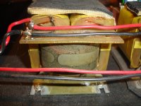
Here's one I had made years ago C core, sep P / S on each leg.
T
Attachments
Yeah you can do that too but there's still capacitive coupling from P ->
core -> Sec.
Which ever way you do it, think physical space between core and winding.
If you use a physically larger bobbin, it can then be cut and packed where
necessary. Once it's varnished the whole thing is set in place.
Do the secondaries have to be isolated from each other?
Also what about cap to ground?
Here's one I had made years ago C core, sep P / S on each leg.
T
Yes the secondaries (the 4 each 6VAC/4A) have to be isolated from each other and to the Rest of the World (RoW). Max acceptable cap to RoW is like 50pF. I *could* go with 4 transformers, each with one 6VAC/4A secondary, same isolation and cap requirements.
I tried to google for diy transformer parts like cores and bobbins but can't find any. Anybode has a link?
jan didden
[snip]20 W is really easy to transfer using high current mosfet drivers like ixdn414 or UC3710 etc. feeding relatively small ferrite ring core with very few primary and secondary turns. All you need is Schottky input logic gate + flip-flop to get 50/50 ratio and two drivers. Primary voltage 12-15 VDC. Or self-oscillating ir2153 (if memory serves right) to control the same drivers. Use the core (isolated internal conductor) from RG59 as primary and secondary wires.
That sounds interesting. You say I can use coax as a kind of 'bi-filar' wound combination of prim and sec? Isn't the inner core 'screened' from the outer screen in the cable?
jan didden
Here's one I had made years ago C core, sep P / S on each leg.
T
OK - I just measured that transformers total P-S capacitance, and it is
around 58pF - pretty good.
They would also be somewhere near 20VA.
So it looks like you should acheive your goal without too many problems.]
Terry
This is also interesting reading:
http://e2e.ti.com/support/interface/industrial_interface/m/videos__files/264970/download.aspx
jan didden
http://e2e.ti.com/support/interface/industrial_interface/m/videos__files/264970/download.aspx
jan didden
OK - I just measured that transformers total P-S capacitance, and it is
around 58pF - pretty good.
They would also be somewhere near 20VA.
So it looks like you should acheive your goal without too many problems.]
Terry
Terry where did you get your xformer parts?
jan didden
That sounds interesting. You say I can use coax as a kind of 'bi-filar' wound combination of prim and sec? Isn't the inner core 'screened' from the outer screen in the cable?
jan didden
No, you should strip outer jacket and outer wowen braid. You'll get wire with 2.5 mm thick PE insulation. Wind primary side on the left side of O and secondary on the right side of O.
Like that:
primary here ->O<-secondary here
P.S. I am not warning you about the danger: you want to build elecricution machine anyway
Terry where did you get your xformer parts?
jan didden
Those were made by a small local company called Alkay transformers. I used to
work there years ago.
But any jobbing type transformer company will be able to help youI am sure,
just be very clear about the low C requirements.
Terry
I can make up a care package for transformer building for you. However you will be better off with a local builder purchasing materials that he is familiar with. I do think that if Pieter can obtain a big enough double C core that will be your best bet. I can provide the Nomex 418, which is used because of it's corona quenching capability, but it is likely also available in Europe. The European twin well bobbins, molded in the latest fire retardant materials are your best bet for winding forms unless you use a double C core with three bobbins, one for each leg.
We have made up packages for shipment into Russia, supplying core, coil wire, bobbins, insulation, tape and lead wire. We haven't made any high voltage transformers for perhaps 15 years, so we don't have the lead wire any more.
Bud
We have made up packages for shipment into Russia, supplying core, coil wire, bobbins, insulation, tape and lead wire. We haven't made any high voltage transformers for perhaps 15 years, so we don't have the lead wire any more.
Bud
I can make up a care package for transformer building for you. However you will be better off with a local builder purchasing materials that he is familiar with. I do think that if Pieter can obtain a big enough double C core that will be your best bet. I can provide the Nomex 418, which is used because of it's corona quenching capability, but it is likely also available in Europe. The European twin well bobbins, molded in the latest fire retardant materials are your best bet for winding forms unless you use a double C core with three bobbins, one for each leg.
We have made up packages for shipment into Russia, supplying core, coil wire, bobbins, insulation, tape and lead wire. We haven't made any high voltage transformers for perhaps 15 years, so we don't have the lead wire any more.
Bud
Thanks Bud, that's usefull info. Pieter is also looking into it, let's see what he comes up with.
jan didden
- Status
- This old topic is closed. If you want to reopen this topic, contact a moderator using the "Report Post" button.
- Home
- Design & Build
- Parts
- Low-capacitance transformer?