Hi folks. I am working on a project that I cannot seem to find a consitent answer for, and I would greatly appreciate any help that anyone can provide. I have a footswitch for a guitar amplifier which changes channels using a SPDT momentary switch. I want to add an LED indicator so that I can tell when the amplifier has changed state. SO, I have ordered a DPDT momentary switch, to allow for the addition of an LED, but I need help with getting the momentary pulse to somehow keep the LED lit until the switch is pressed again. I hope that is clear. I have been looking around, and found many different answers on how to do this, but my knowledge of circuits, and gates is very basic, so I am hoping that someone who knows what they are talking about can take me by the hand and tell me what I need. I have a limited amount of space, so something like a cmos IC that is small would be ideal. Trouble is I don't know how I would need to hook it all up. I will be using a 9v batter for the power source....so basically I want to figure this out using the 9v battery, momentary switch, and LED, plus whatever else is needed to make the light go on with one push of the switch, and off with the next...etc..
THANKS to anyone who might be able to hlep!
THANKS to anyone who might be able to hlep!
My first thought would be to use a clocked T flip flop, which has one input, one output, and a clock input. If the input is low, the output never changes, but if the input is high, the output will toggle on each clock pulse. You'll also need a source of 5V power for standard logic circuits, so I'd get a 7805 linear regulator (one of the low current ones that comes in a TO-92 package will work fine) to do that.
You can make a T flip flop from a J-K flip flop, which is a very common TTL logic circuit you could get for less than a buck. It will come as a DIP package with two flip flops, so just ignore one of them. Tie the two inputs (J and K) together and then connect that to 5V through a 1K or so resistor to set them high. Connect your switch output to the clock input on the flip flop, and connect the flip flop output (Q or Q', one is just the inverted version of the other) to the cathode of the LED. Then just connect the LED anode to 5V through the proper resistor, connect the chip to power and ground, and you should be all set. I'd make a diagram but I am using my phone right now so that wouldn't work.
EDIT - I'd try it and see what happens, but you might need to debounce your switch (when a switch closes the contacts actually bounce off of each other and can generate a couple very brief pulses that are typically insignificant, but a high speed logic circuit like the flip flop can interpret them as multiple presses). You'd just have to add one more small chip and a tiny capacitor and resistor, as outlined here:
How to debounce a switch
Last edited:
The power source is a 9 volt battery so not much capacity is available, maybe 500mAH. It is important to minimize the current drain so I suggest a CD4027 fllip flop. It will run directly from the battery, eliminating the quiescent current of the voltage regulator.
If debouncing is needed, try just a R-C filter at the flip flop clock pin. Keep the resistor at or above 10K to minimize current drain. Put a small (100 Ohm) resistor in series with the switch to limit discharge current from the capacitor.
The LED itself should be one that has high efficiency to run at low current.
View attachment 203683
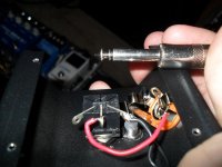
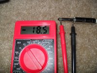
Thanks so much for your help guys! I think I am going to try picking up a couple of the recommended flip flops and see if I can get this thing working. I don't really know much about de-bouncing the circuit, but I have read up on it a little, and seems like it's nothing too complicated. I took a couple photos of the project also just to give a little more insight as to what I am working with. In addition it was suggested that there might be current coming from the amp which could be used to power the LED. So I put a multimeter to it and it read -18.5 DCV...I don't know if that is useful or not, but I figured I would throw that on here in case it gives anyone an idea of a better way to approach the project.
Attachments
I have to take a different approach. All that happens by adding an LED and flip flop is that it tells us the button was pushed. But it doesn;t tell us whether the amp responded or not.
It would be good to know the amp we are working with here. What amp is it?
Are there already existing indicator LEDs on the amp control panel? I'd be tapping into them. They are already switched by the amp switching logic.
It would be good to know the amp we are working with here. What amp is it?
Are there already existing indicator LEDs on the amp control panel? I'd be tapping into them. They are already switched by the amp switching logic.
The amplifier is a Blacktar HT-5 combo. There is a LED on the control panel of the amp, but I am trying to get this done by modifying the footswitch only. At this point I don't want to void the warranty of the amplifier by modifying any internal components. It would be ideal to tap into the LED on the control panel since you would never have to worry about the 2 being out of sync, but since the fix for them being out of sync would be a simple push of a button that would only be necessary once per use, so I can be happy with that if i get it working.
Thanks,
Thanks,
- Status
- This old topic is closed. If you want to reopen this topic, contact a moderator using the "Report Post" button.
- Home
- Design & Build
- Parts
- Default LED on/off using momentary switch help please