i've been seeing a lot of analog design centered around this "device" lately. it seems the current conveyor is the new "building block" as the op amp was years ago. i'll post later when i find a particular schematic i'm looking for, but these devices seem to be a series of cascaded current mirrors. right now i have to leave for work...
some years ago, there was one that generated some interest before the company went "away". i wonder if wadia bought the rights to the design or something? the part number was PA630 and PA630A. allegedly, these parts made nice i-v converters for cd players and such.
alas, that was one sample i never got ...
mlloyd1
alas, that was one sample i never got ...
mlloyd1
Hi unclejed613,
---it seems the current conveyor is the new "building block" as the op amp was years ago.---
That is what was thought when first current conveyors appear, I should say about twenty years ago. Concept and designing with them are as simple as with op-amp, even easier. However, if objective performances are sought, they're not the winners.
However a fascinating use of them is found in the error correction of Jan Didden's Pax amplifier.
I have collected some documentation about them, email me if you're interested.
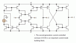
ok, here's the circuit i was looking for. it would be interesting to build one of these with discrete components and experiment with it. from what i've been reading about CCs, the bandwidth is only limited by the Ft of the transistors. i'll have to look further to see how they're used as amplifiers, etc...
Ib at the left is an external current source. X and Y are inputs (but Y can also serve as an output i think) and the Z terminals are outputs. i've seen the equivalent circuit of this drawn as a transistor with -Z as the collector, and Y as the emitter and X as the base. it would be interesting to use this as a "transistor" with an inverting and noninverting "collector".
i wouldn't want to use a transistor array for this as most of them contain a parasitic substrate diode, which requires the substrate to be reverse biased to prevent damage to the device.
Attachments
Last edited:
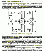
here's a little more on the device i was referring. at the time, they used a high speed process to make good pnp as well as npn parts.
Circuits and systems tutorials - Google Books
Circuits and systems tutorials - Google Books
some years ago, there was one that generated some interest before the company went "away". i wonder if wadia bought the rights to the design or something? the part number was PA630 and PA630A. allegedly, these parts made nice i-v converters for cd players and such.
alas, that was one sample i never got ...
mlloyd1
Attachments
i wouldn't want to use a transistor array for this as most of them contain a parasitic substrate diode, which requires the substrate to be reverse biased to prevent damage to the device.
THAT 300 series matched arrays do not have a diode. It consists of 4 separate dies and do not share the same substrate. Pin 4 is connected to pin 11 internally as the 'substrate' but it should still be referenced somewhere to reduce noise.
check also out the PAX amplifier from Jan Didden (diyaudio member "Jannemann")
http://www.diyaudio.com/forums/soli...k-called-pax-what-about-vitus-ss-101-a-2.html
http://www.diyaudio.com/forums/soli...k-called-pax-what-about-vitus-ss-101-a-2.html
interesting use of a CC for feedback. i didn't quite appreciate the later use of spice behavioral sources for an amplifier though. B sources are "ideal" devices. i can make a perfectly linear amplifier from a B source, if there were such a thing in real life. i'll probably get some time later this week to experiment with the schematic i found in EDN magazine. i've been working on some other projects.
ok, i modeled one in LTSpice, and i guess i need to read a bit more, because i'm just "not getting" something here. i can get it to operate linearly by playing with load resistors and current levels, etc i put a bias current at the Ib node, sink the Y node to ground with a 1k resistor, input a sine current at X, and i get sine waves out across 1k load resistors at the +Z and -Z outputs... yippie.... but each output is close to one rail or the other. to be somewhat realistic, i used 2N3904/3906 transistors. i guess i was expecting something that would swing rail to rail (which it does nicely with no load resistors, but it's a square wave)...... hmm maybe it gets voltage gain based on the ratio of input resistors to output resistors????
any clues? it looks like this would make a nice DSB modulator....
any clues? it looks like this would make a nice DSB modulator....
aha!...
changing the load resistors was the trick... this would make a real nice bridged amp with only one input stage. i had one of the PNP transistors still a default PNP, and that's why the odd offset problem as well as the -Z output having half the waveform.
so changing the output loads changes the "gain" (the input is a current and the output is converted to a voltage)
some years ago, there was one that generated some interest before the company went "away". i wonder if wadia bought the rights to the design or something? the part number was PA630 and PA630A. allegedly, these parts made nice i-v converters for cd players and such.
alas, that was one sample i never got ...
mlloyd1
Yes the PA630 was sold to Wadia, they use(d) it as an I/V in their DACs years ago, called it the Swift Current to Voltage converter. Don't know if they still use it.
I still have some PA630 chips, happy to send you a couple if you want to play with them.
Then again, an AD844 consists of a current conveyer followed by a buffer and you can actually buy them
Check out the OPA866 also; it's a current conveyor but marketed as a diamond transistor. Same beast.
jd
ok, here's the circuit i was looking for. it would be interesting to build one of these with discrete components and experiment with it. from what i've been reading about CCs, the bandwidth is only limited by the Ft of the transistors. i'll have to look further to see how they're used as amplifiers, etc...[snip.
Unclejed,
The reason for the high bandwidth is that there is little voltage swing in the circuit, so parasitic capacitances (that would have to be charged/discharged with voltage swing) have much less impact. CC's can have very high slew rate; the AD844 CC has 2000V/uS...
If you look to the simplified schematic of a CFB opamp you'll also find a CC there, and very high slew rate...
jd
another interesting idea is that a CC is the equivalent of a transistor, with an interesting twist... a transistor with differential outputs (collectors)...
Ohhh yes. A diamond transistor is conceptually a CC is conceptually an ideal transistor.
- Status
- This old topic is closed. If you want to reopen this topic, contact a moderator using the "Report Post" button.
- Home
- Design & Build
- Parts
- current conveyors
 Simply cascode if more than 10Vds needed.
