Hello everyone. I've been reading this forum for some time, but this is my first post. My electronics knowledge isn't quite up to the level of most here, so bear with me") I'm trying to test a 12v in, +/-15v out DC/DC converter to see if it's faulty. It's an outboard unit for a car cd player. It has the following 6 wires on the output side:
I'm trying to test a 12v in, +/-15v out DC/DC converter to see if it's faulty. It's an outboard unit for a car cd player. It has the following 6 wires on the output side:
yellow/red
yellow/black
solid yellow
solid black
black/white
blue/yellow
I tested them with DMM and both black wires are grounds, and I'm getting +15v from the solid yellow wire, but nothing from the other two wires. I'm guessing one of the black wires (black/white?) is for reference, and the blue/yellow wire is the turn-on lead for the converter.
My question is, can this converter be tested with a DMM, or do I need to use a dummy load and/or an o-scope to test it? If it can be tested with a DMM, how exactly would I go about it? TIA
I'm trying to test a 12v in, +/-15v out DC/DC converter to see if it's faulty. It's an outboard unit for a car cd player. It has the following 6 wires on the output side:yellow/red
yellow/black
solid yellow
solid black
black/white
blue/yellow
I tested them with DMM and both black wires are grounds, and I'm getting +15v from the solid yellow wire, but nothing from the other two wires. I'm guessing one of the black wires (black/white?) is for reference, and the blue/yellow wire is the turn-on lead for the converter.
My question is, can this converter be tested with a DMM, or do I need to use a dummy load and/or an o-scope to test it? If it can be tested with a DMM, how exactly would I go about it? TIA
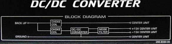
Besides the previously mentioned six wires that connect to the cd player, there's two more wires for power and ground (yellow and black) on the other side of the converter. Here's a picture of the block diagram on the converter:
An externally hosted image should be here but it was not working when we last tested it.
Hmm.. I guess I can't edit my post. Here's the picture again:
An externally hosted image should be here but it was not working when we last tested it.
- Status
- This old topic is closed. If you want to reopen this topic, contact a moderator using the "Report Post" button.