i have preamp that has too much gain that i only have small adjustment range in the volume control.
the preamp i build is http://www.diyaudio.com/forums/showthread.php?postid=1609806#post1609806
according to this link:
http://www.tweakaudio.com/Attenuator info.html
we can devide the voltage to lower the gain..
i am newbie, so i seek confirmation before i try stuff not in my knowledge.
can i just add 1K in series to the output and 300R to the ground to lower 13db according to the attenuator info link above?
thanks alot in advance
hello.
that attenuator is a heavy load,i would not do it .
do you use this tubepreamp with musical instruments,or with a cdplayer or so?
with a cdplayer you need not this high input impedance(100k).
try to build in a resistor from potentiometer- output to ground(grid to ground).
perhaps beginn with 50kiloohm,that lowers the inputsignal a little bit.because the problem is that your inputsignal is too big.if it is not enough,try it with 20k.
greetings.........
hi mfj
thanks for the reply. i am using a mac and a dac as source. then feed the preamp with gain 8.
sorry bout my ignorant, just wanted to confirm, do you suggest to do the mod in the potentiometer? i am using LDR as pot with 27K in series of the signal.
do you suggest to put a resistor from grid to ground after the potentiometer, in my case LDR, with value of 50K or lower?
with my limited knowledge i think my source can be considered smaller than normal cd player. as some people are asking to raise the gain on the DAC.
hence i think the gain of the pre thats too big. as i have another preamp that has gain of two and do not have the problem with the volume control. in this case normal listening position is 1 o;clock
thanks in adv
erwin
hello.
my suggestion was valid for the schematic you showed..........if you changed something that i did not know............?;
the text is not easy to translate for me (e.g.:what ldr? - ldr is a designation for light dependent resistor in electronics,but i think you did not use this......).
there is a schematic - perhaps it can help you..........
greetings..........
Attachments
mjf said:hello.
my suggestion was valid for the schematic you showed..........if you changed something that i did not know............?;
the text is not easy to translate for me (e.g.:what ldr? - ldr is a designation for light dependent resistor in electronics,but i think you did not use this......).
there is a schematic - perhaps it can help you..........
greetings..........
hi mjf
I use the ldr volume control. Not sure how it work but it replace the 100k pot and sound alot nicer
Thx for the schem. Will learn it
Hi andrewtAndrewT said:Hi,
do you have too much volume or too little volume with the existing stage gains?
I have too much gain. Need to attenuate. Learn that use two resistors can attenuate the signal. Eg. 24k series with signal input then 1k to ground before pot or attenuator help reduce ard 28db with Zin = 25k and Zout 960 ohm
no nfb!
The high gain is easiest to control with a negative feed back loop, according to the circuit ther is no feed back at all, and that's never a good ide or design(when desining a preamp or any amp you should always try to get as much gain as possible in open loop mode, which can go as high as 100 000 times(in a B-class Amp) then you reduce the gain to 10 times or xlog * 20dBV - gain. Comes to 20dB voltage gain. Which is more then enough for a preamp if you don't need to amplify a giutar or Recordplayer/tapeplayer or something like that, most signal to day is way above 50 mV and 10 times 0.05V gives 0.5V and if the amp driven with this cascode coppled "preamp" needs more well increas the N.F.B.! Well I did stay from the subject there but this is my recomendation: USE negative feed back! Connect a pot say 470k to 1 meg from the output, after the hugh 22µF cap.(increase the 18k resistar to 47k and change the 22µF cap. to 1µF fc = 1/(2*pi*R*C) = 3.4 Hz and that's enough! The 47k R, is there to keep the cap. charged! aand effects the output imp.) to the (wiper)grid on the lower valve(or Tube as the say in the US) in the cascode-amp. Cascode coppled amps with valves can be compared with darlington coppled transistors, which means if the gain is 50 in each valve(transistor) the total A( = amplification) is 50 times 50 comes to 2500! and vith only 75 ohms resitors, well you can do the math.... the voltage drop over Rk1(the top 6T4) is 20mV * 75 = 1.5V and that's the limit for the amp! So you need a feed back loop. And then you got the A in each valve to consider so, no wonder you can't move the volyme pot...., you can try to increase Rk2(lower 6T4) to 2.2k or higher to minimize the current flow and lower the plate voltage but that's no good way to fix the problem, n.f.b. IS the only way, I haven't read all the others contributions... but this is mine! And I stand by it! Good luck!
The high gain is easiest to control with a negative feed back loop, according to the circuit ther is no feed back at all, and that's never a good ide or design(when desining a preamp or any amp you should always try to get as much gain as possible in open loop mode, which can go as high as 100 000 times(in a B-class Amp) then you reduce the gain to 10 times or xlog * 20dBV - gain. Comes to 20dB voltage gain. Which is more then enough for a preamp if you don't need to amplify a giutar or Recordplayer/tapeplayer or something like that, most signal to day is way above 50 mV and 10 times 0.05V gives 0.5V and if the amp driven with this cascode coppled "preamp" needs more well increas the N.F.B.! Well I did stay from the subject there but this is my recomendation: USE negative feed back! Connect a pot say 470k to 1 meg from the output, after the hugh 22µF cap.(increase the 18k resistar to 47k and change the 22µF cap. to 1µF fc = 1/(2*pi*R*C) = 3.4 Hz and that's enough! The 47k R, is there to keep the cap. charged! aand effects the output imp.) to the (wiper)grid on the lower valve(or Tube as the say in the US) in the cascode-amp. Cascode coppled amps with valves can be compared with darlington coppled transistors, which means if the gain is 50 in each valve(transistor) the total A( = amplification) is 50 times 50 comes to 2500! and vith only 75 ohms resitors, well you can do the math.... the voltage drop over Rk1(the top 6T4) is 20mV * 75 = 1.5V and that's the limit for the amp! So you need a feed back loop. And then you got the A in each valve to consider so, no wonder you can't move the volyme pot...., you can try to increase Rk2(lower 6T4) to 2.2k or higher to minimize the current flow and lower the plate voltage but that's no good way to fix the problem, n.f.b. IS the only way, I haven't read all the others contributions... but this is mine! And I stand by it! Good luck!
hi joyce_666
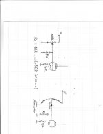
i attached the schem. is this what you recommend? this is my 1st tube preamp build. so please bare with me.
the actual cap on the output is 2.2uf
the current my pre running now is 34mA for both channel. hence only 17mA per channel i assume (as changing to other tube can differ the current from 25-34mA could be bad tubes). as i am using same psu for both channel.
the cathode voltage is around 74-90v depending on the tubes and yes the different between the resistor is about 1.3v. do you suggest dropping another 75v (if this is correct, pls correct if wrong) by replacing the 75R to 2.2K?
thanks you very much for the suggestion
Erwin
Attachments
- Status
- This old topic is closed. If you want to reopen this topic, contact a moderator using the "Report Post" button.
- Home
- Design & Build
- Parts
- voltage devider or line attenuator help