Hi,
boy oh boy I like doing this. Sure beats scanning the web for an answer. I mean how do you formulate a search that has to do with a capacitor on the input of a transistor? I mean, there could be many reasons...
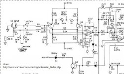
So anyway here it is. I was looking at some schematic diagrams on Carvin's website (well actually, carvinservice.com) and found a couple of things that I couldn't understand. I am not dumb in electronics, having a degree in electronics from a recognized College (well at least in Maple syrup land) but I am not knowledgeable about all the little mods and tricks that are done to correct the effects of frequency and input capacitance and whatnot. So what is the function of C4?
also I noticed no less than 4 coupling capacitors before the fader potentiometer. this does include the ones for the microphone, but whatever. Isn't that a lot? And it still has a lot of travelling to do. Now, this design uses opamps that are powered by a bipolar supply. Isn't it kind of useless to isolate stages with capacitors when ther isn't any difference in DC levels between them? Besides, the resistors that are between the stages (R18; R19 and R22) can take a few volts, if even that, right?
And same goes with the fader.
what's a few measly fractions of a volt going to do when you've got resistors isolating stages.
I'd really like to know!
thank you
boy oh boy I like doing this. Sure beats scanning the web for an answer. I mean how do you formulate a search that has to do with a capacitor on the input of a transistor? I mean, there could be many reasons...
So anyway here it is. I was looking at some schematic diagrams on Carvin's website (well actually, carvinservice.com) and found a couple of things that I couldn't understand. I am not dumb in electronics, having a degree in electronics from a recognized College (well at least in Maple syrup land) but I am not knowledgeable about all the little mods and tricks that are done to correct the effects of frequency and input capacitance and whatnot. So what is the function of C4?
also I noticed no less than 4 coupling capacitors before the fader potentiometer. this does include the ones for the microphone, but whatever. Isn't that a lot? And it still has a lot of travelling to do. Now, this design uses opamps that are powered by a bipolar supply. Isn't it kind of useless to isolate stages with capacitors when ther isn't any difference in DC levels between them? Besides, the resistors that are between the stages (R18; R19 and R22) can take a few volts, if even that, right?
And same goes with the fader.
what's a few measly fractions of a volt going to do when you've got resistors isolating stages.
I'd really like to know!
thank you
Attachments
Hi gain-wire,
C4 is an RF filter working with the ferrite beads, it's function is to make the high frequencies common mode to be rejected by the differential pair. Don't forget that balanced mikes often run a long way between the mike and preamp circuits.
C1 blocks the DC phantom supply from the output of anything plugged into the line in jack. That would be a nasty surprise if you left the phantom on and plugged a non-phantom powered device. around 50 VDC would probably damage the output coupling caps on whatever you plugged in, and the output circuit or op amp.
C2 and C3 block your phantom supply voltage from your internal circuitry. That's approximately 50 VDC there. C5 keeps the DC from appearing across that control. Any DC across a variable control will create noise. Enough so that the perfectly good control sounds bad.
C7 blocks the DC offset from A123 from the tone circuit. Again, any DC offset across a variable control will make it noisy. The DC output voltage from A123 is not guaranteed as it's inputs are taken from the collectors of Q1 and Q2. They are probably not in perfect balance to begin with. Therefore, expect some DC voltage on the output of A123.
So you can see that there are no unnecessary capacitors installed there. They are all required
-Chris
add to that, the noise spectrum of most op-amps rises exponentially at low frequency (1/f noise) and so you can only meet the noise and dynamic range specs by controlling your LF bandwidth.
...and just to reinforce Anatech's sage advice: DC on volume pots is very, very bad.
Those few input caps are actually providing a lot a value")
...and just to reinforce Anatech's sage advice: DC on volume pots is very, very bad.
Those few input caps are actually providing a lot a value
Hmm, thanks guys, I wanted to thank you earlier, but I was so busy! Anyway, I'd really like to know why it's such a big deal to have DC on the potentiometers. Is it because it "zaps" the dust particles on the carbon strip? I'm trying to take an educated guess here. Also how much DC is necessary to cause problems? Like 100millivolts? I find that really hard to believe, yet, I am the kind of person who will try it just to find out!
So, we are forced to necessarily listen to the sound of capacitors on anything that has a volume control? such a bother...
So, we are forced to necessarily listen to the sound of capacitors on anything that has a volume control? such a bother...
Hi gain-wire,
The trouble with people who like to modify things is that they often do not understand how a circuit is designed, or why the parts are installed. Let me assure you that if these capacitors were not absolutely required, they would not be installed. No manufacturer installs anything unless there was no other choice. Reading information on the internet posted by people who are not trained in audio electronics for advice is pretty silly if you ask me. Then a funny thing happens, The advice from someone who only thinks they know what they are doing has more weight, or validity, than people who actually work in the field. Especially if that person who works in the industry is a real, honest to god engineer.
While getting rid of capacitors that are not required in an audio path is generally a good idea, it is only one thing that needs to be considered in a design or modification. Make no mistake, designing and performing a modification is engineering. Without good knowledge of what you are doing, you stand a pretty good chance of compromising the victim device.
-Chris
Because it makes noise when the wiper moves, and we don't like that sound. It also causes a shifting DC level that will be amplified and create a variable DC offset. We don't like that either, nor do many amplifier protection circuits.I'd really like to know why it's such a big deal to have DC on the potentiometers.
Not really.Is it because it "zaps" the dust particles on the carbon strip?
It depends a great deal on the circuit and how much gain there is after the control. 10 mV is enough to cause trouble sometimes.Also how much DC is necessary to cause problems? Like 100millivolts?
Easy enough to find out. Experiment away.I find that really hard to believe, yet, I am the kind of person who will try it just to find out!
What does a capacitor sound like? Then again, what does an audio control sound like, or a switch, wire, PCB material, connectors ... To be honest with you, often there are worse things in a circuit than a capacitor (unless you use the wrong type for the job). Capacitors are installed because they are required, not because we like to trouble ourselves.So, we are forced to necessarily listen to the sound of capacitors on anything that has a volume control?
The trouble with people who like to modify things is that they often do not understand how a circuit is designed, or why the parts are installed. Let me assure you that if these capacitors were not absolutely required, they would not be installed. No manufacturer installs anything unless there was no other choice. Reading information on the internet posted by people who are not trained in audio electronics for advice is pretty silly if you ask me. Then a funny thing happens, The advice from someone who only thinks they know what they are doing has more weight, or validity, than people who actually work in the field. Especially if that person who works in the industry is a real, honest to god engineer.
While getting rid of capacitors that are not required in an audio path is generally a good idea, it is only one thing that needs to be considered in a design or modification. Make no mistake, designing and performing a modification is engineering. Without good knowledge of what you are doing, you stand a pretty good chance of compromising the victim device.
-Chris
Obviously stuff I never learned in College... well mostly, the idea behind my "anti-capacitor" problem came mostly out of reading stuff in electronics and audio magazines that claimed they had no, or much less capacitors on either the input or the output of the device. Kind of like a DC coupled amplifier performs better at any frequency than an AC-coupled Amplifier. the output capacitor maes for different phase shifts depending on the frequencies contained in the signal. Or at least that's what I remember learning!
Besides, I am mostly the type that thinks the music sounds good if I like the music, not whether it's coming out of a sharp mini system or a McIntosh system fed by a PEL blue-laser diode cd player.
I will stop blabbering now.
Thanks again!
Besides, I am mostly the type that thinks the music sounds good if I like the music, not whether it's coming out of a sharp mini system or a McIntosh system fed by a PEL blue-laser diode cd player.
I will stop blabbering now.
Thanks again!
Hi gain-wire,
No problem.
Something to remember. Once you graduate from university or college, you are now ready to begin learning. Doesn't matter what field. The thing I love about electronics (and most everything) is that you never stop learning.
Common sense is your best guide, that and scientific information sources will tend to teach you correct facts. Always try to keep things in perspective and related to the intended use. Keep reliability of the device you work on your primary concern.
I once used an open reel machine in my car, not very realistic. I don't do that any more. In fact, my last two cars have had their factory sound systems intact the entire time. MP3s work great for walking music I guess. I don't like the sound, so I listen to nature instead. The clock radio wakes us up, the surround system sounds okay - it goes ting and boom at the right times. The main sound system sounds - really good. Each system has it's place.
-Chris
No problem.
Something to remember. Once you graduate from university or college, you are now ready to begin learning. Doesn't matter what field. The thing I love about electronics (and most everything) is that you never stop learning.
Chances are that the McIntosh system will sound better though!Besides, I am mostly the type that thinks the music sounds good if I like the music, not whether it's coming out of a sharp mini system or a McIntosh system
Common sense is your best guide, that and scientific information sources will tend to teach you correct facts. Always try to keep things in perspective and related to the intended use. Keep reliability of the device you work on your primary concern.
I once used an open reel machine in my car, not very realistic. I don't do that any more. In fact, my last two cars have had their factory sound systems intact the entire time. MP3s work great for walking music I guess. I don't like the sound, so I listen to nature instead. The clock radio wakes us up, the surround system sounds okay - it goes ting and boom at the right times. The main sound system sounds - really good. Each system has it's place.
That is not true, especially for audio reproduction. You have to watch out for blanket statements like these.Kind of like a DC coupled amplifier performs better at any frequency than an AC-coupled Amplifier.
-Chris
gain-wire said:So, we are forced to necessarily listen to the sound of capacitors on anything that has a volume control? such a bother...
Not necessarily, it is possible to design an audio chain without capacitors but the circuit complexity goes way up. The added circuitry (many active devices) would add noise and distortions of their own. An interesting design exercise though
Back in the fairly early opamp days it became popular to try and reduce the number of capacitors in the signal path. Pretty well without exception all the designers admitted it was a mistake in later years.
In a modern amplifier there will actually be very few anyway, without trying hard to reduce them.
Bear in mind, reducing a few capacitors in your amplifier still leaves the hundreds (or thousands) it went through in the recording process.
In a modern amplifier there will actually be very few anyway, without trying hard to reduce them.
Bear in mind, reducing a few capacitors in your amplifier still leaves the hundreds (or thousands) it went through in the recording process.
Hi Nigel,
You're going to have him jumping off a bridge if you keep on pointing out reality.
Long live the 5534A, 5532A and LM318 op amps!!!
-Chris
Many of which are tantalums in the older consoles, never mind the outboard gear and the miles of Beldin wire.Bear in mind, reducing a few capacitors in your amplifier still leaves the hundreds (or thousands) it went through in the recording process.
You're going to have him jumping off a bridge if you keep on pointing out reality.
Long live the 5534A, 5532A and LM318 op amps!!!
-Chris
- Status
- This old topic is closed. If you want to reopen this topic, contact a moderator using the "Report Post" button.
- Home
- Design & Build
- Parts
- Calling all electronics wizards! (circuitry question)