consider what peak transient current that the speaker may demand.
An amp fed from 24Vdc could maybe achieve 20Vpk into a load.
If the speaker is 8ohm the max current could be around 20/8/0.35 ~=7Apk.
Where will this peak current come from?
If the speaker is 4ohm the output current can be around 14Apk.
An amp fed from 24Vdc could maybe achieve 20Vpk into a load.
If the speaker is 8ohm the max current could be around 20/8/0.35 ~=7Apk.
Where will this peak current come from?
If the speaker is 4ohm the output current can be around 14Apk.
AndrewT said:consider what peak transient current that the speaker may demand.
An amp fed from 24Vdc could maybe achieve 20Vpk into a load.
If the speaker is 8ohm the max current could be around 20/8/0.35 ~=7Apk.
Where will this peak current come from?
If the speaker is 4ohm the output current can be around 14Apk.
Where is the 0.35 factor coming from?
Hi Eva,
that appears repeatedly in the Forum from expert designers. The GEM in particular is designed to be tolerant of that type of effective impedance variation. They seem to have agreed that fast stopping and fast starting (audio) transients deliver large currents to the crossover/speaker combination.
Just a couple of days ago there was a further reference that the 0.35 factor is a bit light for severe reactance speakers and that the factor could be around 0.2 to 0.25 for severe speaker loading.
Even the relatively gentle impedance curve of the JBL example used in the test demanded very large current peaks on a few excepts of music signals. It seems that 0.35 may be a closer estimate for moderate or moderate to severe speaker loadings.
I find that using 0.35 demanding enough when taking gain droop back through the stages to the VAS to determine the peak transient currents in the outputs.
If this is a valid way of designing for peak currents, it puts into context the frequently quoted peak currents available from amplifiers when manufacturers deem it worth bragging about.
hi guys
thanks for the reply. but your answer is beyond my understanding. i am still newbie that build few from schematic and do not really quite understand all the terms
please bare with my questions:
peranders, do you mean using two transformer or dual secondary? can i achieve this with ct transformer as i have on CT PT at hand?
AndrewT, this psu is intended for lm1785. does it still apply to your answer?
thx in adv
erwin
AndrewT said:Hi Eva,
that appears repeatedly in the Forum from expert designers.
This is a myth to sell "high current" amplifiers. I have been repeatedly unable to get such a result.
You can design a passive crossover to exhibir reactive low-impedance dips at certain frequencies, but this is neither common practice nor a good design criteria. Voice coil resistance always limits current and its value increases due to self heating when the speaker is fed some power.
One of the systems that I have used for years is a 4-channel chip-amp setup. It's fed +/-40V from LM338K regulators. Output capacitance is 10.000uF per rail. With music it was just not possible to fold back the regulators even when driving 4 ohms on all channels above clipping. Crossover was active for bass/mid and passive for mid/high (2+2 channels).
Eva said:
One of the systems that I have used for years is a 4-channel chip-amp setup. It's fed +/-40V from LM338K regulators. Output capacitance is 10.000uF per rail. With music it was just not possible to fold back the regulators even when driving 4 ohms on all channels above clipping. Crossover was active for bass/mid and passive for mid/high (2+2 channels).
Hi Eva
do you mind share the schematic for lm338K regulators circuits?? i am interested in building one. does the PT use dual secondary or CT? thx
You only have to download a datasheet
http://www.national.com/mpf/LM/LM338.html
http://www.national.com/mpf/LM/LM338.html
To get a negative rail first generate two independent (floating) positive regulated rails (from separate transformer windings, rectifiers and LM338), then connect the ground from one rail to the positive from the other, so that they become "stacked".
Instability may result if both regulators share the same heatsink (due to parasitic capacitance).
Instability may result if both regulators share the same heatsink (due to parasitic capacitance).
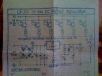
how bout this schematic. sorry abit blur.
its using lm317 and few 2N3055 to boost the current to 20A with six of 2N3055? D5 diode is the other way around (wrong print)
can i use two of this with the stacked configuration to achieve 4A regulated +24vdc 0v -24vdc?
thx
its using lm317 and few 2N3055 to boost the current to 20A with six of 2N3055? D5 diode is the other way around (wrong print)
can i use two of this with the stacked configuration to achieve 4A regulated +24vdc 0v -24vdc?
thx
Attachments
The LM338 itself can provide over 10A transients in the usual working conditions (provided that input voltage isn't too high). Gentle output capacitance helps a lot with transients too because not all current comes from the regulator even at bass frequencies. That's what makes it capable of powering 4 chip amps playing full music output.
- Status
- This old topic is closed. If you want to reopen this topic, contact a moderator using the "Report Post" button.
- Home
- Design & Build
- Parts
- 4A +24v -24vdc regulated psu help for GC