The 0.1 mfd's can be soldered under the PCB on the pins of the IC. Replace the 100 mfd's at the output with the new 10 mfd. Fit new 100 mfd for those at the input.
Fit the regs in place of the transistors you have removed. If you need to bend the legs to get them to fit directly do it neatly using pliers first. The aim is to make it look all original. The connection that was the "base" of the old transistors will become the "ground" pin of each reg and will need linking to the ground track of the PCB ideally where the 10 mfd caps return to.
Fit the regs in place of the transistors you have removed. If you need to bend the legs to get them to fit directly do it neatly using pliers first. The aim is to make it look all original. The connection that was the "base" of the old transistors will become the "ground" pin of each reg and will need linking to the ground track of the PCB ideally where the 10 mfd caps return to.
Pharod,
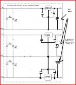
Let's summarize: You have a schematic for a set of straightforward series pass regulators. One for digital circuitry, and two for analog circuitry. In each case, the relatively low gain of the pass transistor (MPSW01) has been augmented with the addition of a general purpose op-amp. No doubt the LF351 was chosen because it is simple to use - i.e., it is stable at all gains, will drive capacitive loads rather well and is very inexpensive. However, don't let the cost fool you. This is a very fine op-amp.
Replacing it with the AD744 would be ill advised if for no other reason than that the enhanced performance and added cost will get you nothing. If as you indicate, it is also not available from Digikey, then you also have to add to the list the difficulty of obtaining the part.
Now, some other issues. It has been stated that the large feedback capacitor (C23) will destabilize the op-amp. While another poster correctly indicated that this is in fact false, a few issues need clearing up. As a general rule, a capacitor in the (negative) feedback limb of an op-amp will ALWAYS STABILIZE the op-amp. In fact, it forms a low-pass filter whose 3dB corner frequency is 1/(2piRC). On the other hand, a capacitor from the output of an op-amp to ground will frequently severely destabilize the op-amp, requiring measures to stabilize things. (This is probably what the incorrect post was referring to.) The large feedback capacitor will indeed reduce noise above the 3dB point defined by RC. However, it also will have a negative impact on transient response. In any case, it's probably just fine to leave it alone.
One final note, there is no violation of either common mode or differential mode input voltages in this circuit. The input reference voltage at pin 3, formed from the LED (which by the way can be quite quiet and stable - there is even a post in one of these forums about noise in LED references) will be exactly matched by the output voltage, scaled by the voltage divider formed from R30 and R24. The only time there will be any significant differential input voltage is when the regulator is not regulating, i.e., at power up and during overload. Otherwise the voltage at pins 2 and 3 will be the same. (Well, almost...It will actually be 5.6V divided by the open loop gain of the amplifier. The gain of the pass transistor is usually so low as to not be much of a factor. Usually this winds up being somewhere in the microvolt range.) Since the reference voltage is above ground, and below the positive supply rail (by definition) there is no common mode issue either.
The best suggestion that was made so far in this thread is the one regarding the 3-terminal regulators. If you are really going to build up a new version of this circuit, you should seriously consider these. They will significantly outperform the op-amp+pass transistor, having better transient response, better line regulation, better load regulation and lower noise. They are so simple to use that it is almost embarrassing. Voltage in, ground, voltage out. They require merely an ouput capacitor and maybe an input capacitor (values are recommended on the spec. sheets). What's more, they would replace virtually every component in the regulator section. Just take out everything but C26, put the regulator in where the pass transistor was (pay attention to pin-out!) and ground what was the base lead. You can stick the input capacitor into where D9 was located. For the 5 volt line you will want an LM7805. If the current requirement is low, you can get a 100ma unit in a TO92 package (LM7805L). I believe there's a 1 AMP version in a TO-3 can (LM7805M) and a still larger current version in a TO220 or similar package. They start at about 50 cents - less than the cost of a replacement pass transistor! If you want to do the same for the analog side of things, you will want LM78xx for positive voltages and LM79xx for negative. The "xx" is the voltage, and they come in 5, 8, 12 and 15 volt versions.
but it is only 1,7V above the negative rail, which is tied to ground, and therefore outside the specified input voltage range for the LF351 and most other opamps.sbesch said:
Since the reference voltage is above ground, and below the positive supply rail (by definition) there is no common mode issue either.
Within this circuit the AD744 would opererate outside specifications as well.
This makes opamps swap risky.
regards
Fascinating and educational. I did find the 744s at Digikey afterall. I contacted AD and they said it should work as a swap however I did not show them the circuit.
In any regard I'll build the circuit using the new method and report the results.
You don't think I need that protection diode in the circuit anymore? Even if I put in a FRED?
In any regard I'll build the circuit using the new method and report the results.
You don't think I need that protection diode in the circuit anymore? Even if I put in a FRED?
Juergen Knoop said:
but it is only 1,7V above the negative rail, which is tied to ground, and therefore outside the specified input voltage range for the LF351 and most other opamps.
Alas, Juergen, you are absolutely correct. (There should be a smiley face with egg on it.) I failed to notice the strange connection of V- to ground rather than the negative supply rail. It is so strange to use a 351 in a single supply setting that I simply assumed that no one would ever do such a thing without re-referencing ground. I now agree with you that the circuit as drawn should never have worked at all. I suspect there my be an error in the schematic - not an uncommon thing - and that the actual circuit may have V- connected to the negative rail. Otherwise, why wouldn't they have used an LM358, which is designed for single supply use and includes the +/- rails in the I/O range?
Audio circuit design does not always involve logic and reason. ")
I would stick with Moolys recommondations.
The 78/79XX series is almost troublefree to use.
Any opamp swap in the existing regulator circuit would require tight control with an oscilloscope etc.
Apart from that, LM358 is a really nice opamp.
But people are always longing for the fancy parts instead for the reliable workhorses.
regards
- Status
- This old topic is closed. If you want to reopen this topic, contact a moderator using the "Report Post" button.
- Home
- Design & Build
- Parts
- Need opamp recommendation