This thread is the beginning of a discussion on what ground loops are and how to avoid them. The three areas to be discussed will be the external environment, the internal, and later, how to force ground currents as well as measure them.. While centered on grounding and hum/noise, the concepts are fully applicable to the actual wiring within the components.
I hope everybody chips in, it should be a good learning experience for all.
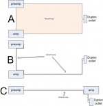
I've posted a pic of three different system configurations. The assumption is 3 prong NEC type units. (two prong applies as well, but the freq response profile will be different, dependent on the impedance to chassis..)
A. This is the typical home setup. The user buys a source and an amp...connects em together with one or two IC,s then runs with it. Notice the ground loop. Any magnetic flux that goes through that loop will create a voltage (current) around that loop. If it's the romex in the wall, oh well.. If an appliance, motor, dimmer circuit goes near that loop, it will make current flow within the ground loop.
It is not obvious how to make either component impervious to that ground current. But nonetheless, current will flow through them. If they are not designed to pass that current without creating magnetic fields inside the chassis, then it will come out in the wash as non-music..
B. This is the same setup, but the pre cord has been moved to wrap around first the IC's, then the amp line cord. Notice that the big loop "antennae" is now missing. If the cords are twisted well, there is nothing an external device can do to generate ground currents in this setup.
C. This is a small varient of B, one I used for a 450 seat venue. I ran a 100 foot extension cord from the stage to the pre/mixer, and wrapped the single ended stereo pair around that cord. Both amp and pre were using the same outlet strip. This prevented the house lights dimmers, AC unit, everything external, from putting any noise into the system.
Note that both B and C are basically limited to 15 or 20 amps worth of equipment. If one requires more, a dedicated group of outlets with one common ground from the outlets back to the breaker panel is needed...one ground only. More than one ground will setup a huge loop to the service panel.
Option B or C will reduce significantly, most hum issues in the home. (not cable, that is a different nut...)
But neither will address well, currents formed by the guts of the equipment. This includes 60 hz, odd harmonics from the line side of the bridge rectifier, even harmonics from the load side of the bridge, nor actual musical content magfield generation on the supply rails back to the line. That's stuff to play with farther down the thread.
Cheers, John
I hope everybody chips in, it should be a good learning experience for all.
I've posted a pic of three different system configurations. The assumption is 3 prong NEC type units. (two prong applies as well, but the freq response profile will be different, dependent on the impedance to chassis..)
A. This is the typical home setup. The user buys a source and an amp...connects em together with one or two IC,s then runs with it. Notice the ground loop. Any magnetic flux that goes through that loop will create a voltage (current) around that loop. If it's the romex in the wall, oh well.. If an appliance, motor, dimmer circuit goes near that loop, it will make current flow within the ground loop.
It is not obvious how to make either component impervious to that ground current. But nonetheless, current will flow through them. If they are not designed to pass that current without creating magnetic fields inside the chassis, then it will come out in the wash as non-music..
B. This is the same setup, but the pre cord has been moved to wrap around first the IC's, then the amp line cord. Notice that the big loop "antennae" is now missing. If the cords are twisted well, there is nothing an external device can do to generate ground currents in this setup.
C. This is a small varient of B, one I used for a 450 seat venue. I ran a 100 foot extension cord from the stage to the pre/mixer, and wrapped the single ended stereo pair around that cord. Both amp and pre were using the same outlet strip. This prevented the house lights dimmers, AC unit, everything external, from putting any noise into the system.
Note that both B and C are basically limited to 15 or 20 amps worth of equipment. If one requires more, a dedicated group of outlets with one common ground from the outlets back to the breaker panel is needed...one ground only. More than one ground will setup a huge loop to the service panel.
Option B or C will reduce significantly, most hum issues in the home. (not cable, that is a different nut...)
But neither will address well, currents formed by the guts of the equipment. This includes 60 hz, odd harmonics from the line side of the bridge rectifier, even harmonics from the load side of the bridge, nor actual musical content magfield generation on the supply rails back to the line. That's stuff to play with farther down the thread.
Cheers, John
Attachments
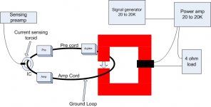
Here's the test setup.
I have the toroid for the current sense pickup, it's a secondary core from an old ATX supply, so it'll definitely have the bandwidth. Center hole is .550 inches, so I figure it'll take most rca's.
Gonna have to wind some copper through that puppy, see what I need to view 20 to 20K down to about 10 microamps. It'll probably require several different windings to do that sensitive at such a range..and I'll have to pickup some kinda preamp circuit also.
Don't know what to use for the drive core yet, I'm scrounging up. I was thinking of cutting one of my plitron 225 va toroids in half, I have eight more..
My intent is to use the drive core also as a test for ground loop susceptibility over the entire audio range....I'll have the amp on, the pre on but not playing anything, and then bring the drive toroid around the line cord slowly...gotta be careful of course, in case the amp is really susceptible..
Cheers, John
ps....btw, this setup is what is needed to verify that an amp design has been made to reject ground currents..it'd be silly to just post pics and verbage...gotta have some data, and heaven forbid.....graphs...
Attachments
bear said:I think ur in the wrong section?
Maybe... thought this was mostly about parts and electronic parts and their application.
Although your post pertains to all types of circuits, I think it is better placed in the solid state section... fwiw, imho, etc...
_-_-bear
I wasn't sure where to post it. Several forums seemed reasonable.
Tube circuits also suffer ground loops. I figured that for the external loop issues, here was most logical...Once I get into the internally generated magfields, then of course solid state low impedance circuits are the most susceptible.
For a discussion that uses "black boxes" without regard to the inner workings as my diagram has, I thought this place was best.
I wonder if perhaps a new forum under other stuff...grounding and noise perhaps...
Cheers, John
I doubt it, because hum in home stereo is not related to hum pickup, but to calvanic coupling and currents flowing because of potential differences, i.e. leakage currents etc.Option B or C will reduce significantly, most hum issues in the home.
Cable wrapping doesn't help with this.
regards
Juergen Knoop said:I doubt it, because hum in home stereo is not related to hum pickup, but to calvanic coupling and currents flowing because of potential differences, i.e. leakage currents etc.
Cable wrapping doesn't help with this.
regards
As I have stated, this technique works excellently when hum is induced as a result of the enclosure of time varying magnetic fields. I have used this technique with success to kill hum in magnetic cartridge phono systems, 100 foot long runs in a building with 25 kilowatts of solid state dimmers, AC power, and even a 250 kilovolt van degraf generator next to the electronics, as well as a 100 microvolt magfield measurement coil system whre the wires traverse 75 feet and past 2 to 5 tesla magnets and 600 amp 480 volt power supplies. (a rather hostile enviro, as 12 pole scr supplies are notorious generators of hash.)
What you are speaking of is something entirely different, but one which will be important to the equipment design aspect, which is making it ignore the current while still allowing it to flow (the NEC defines this as unintended current, and they provide almost ZERO assistance in working around this).. This is also what happens when one connects to the "cable", as they wreak havoc with grounding because they are required to protect against lightning..independent of the power company.
I am the first to admit that what I've stated, that of wrapping the power cables together, or even the pre cable wrapped around the IC's, seems counterintuitive..but it is not. It works, and works very well
But as you point out, it will not counter a hard leakage path, that must be addressed seperately. I started this thread with a basic description of the magnetic coupling effect, so that I could detail the method and equipment necessary to measure the equipment's ability to reject the ground current regardless of the inducement methodology. I chose magnetic induction to create the ground current BECAUSE trying to inject it via wiring means connecting to the circuit, and given the low resistances involved, I prefer the drive NOT alter the loop which we are trying to measure.
Cheers, John
Oh, btw. Within the home, if you measure the safety ground to safety ground potential between two outlets in one room, you will find a voltage. You will find this occurs even if there is no current draw in the wires or the ground...it is because the 60 hz magnetic field in your house (or 50 hz) is coupling to the loop you form when you measure from one ground to the other. Voltages in the 1 to 2 volt range are not uncommon, but for a daisy chained outlet string that would be an IR drop consistent with half a kiloamp or so...which is of course not the case. It is magnetically induced, which is what this thread is all about... my office has two outlets currently unused, on two adjoining walls, they daisy from one to the other, and they run 400 mV to 1.5 V differential depending on the time of day..again, unloaded..
but it needs a current for hum. Connect a class2 thingie to a class1 amplifier and this will result in app. 0,1-0,5mA hum current flowing through the interconnects.Within the home, if you measure the safety ground to safety ground potential between two outlets in one room, you will find a voltage.
regards
If it is magnetic coupling, yes it needs the current. Electric coupling, no current needed.Juergen Knoop said:but it needs a current for hum.
The point is, faraday's law of induction essentially guarantees that if you enclose time varying magnetic field lines with a conductive loop, there will be currents.
The goal of the thread is to figure out how to reduce the currents that will be generated, and how to reduce the equipment sensitivity to those currents.
Juergen Knoop said:Connect a class2 thingie to a class1 amplifier and this will result in app. 0,1-0,5mA hum current flowing through the interconnects.
regards
I believe you meant to say it will result in current flowing on the shield of the interconnects.
And even that case can be dealt with once it is understood w/r to e/m theory. It's trivial to run the shield current over all the IC's with a cylindrical braid, bond that to each chassis, and remove the magnetic coupling.. But I fear I'm jumping the gun with that solution, it'll be along soon enough.
You did notice that I specifically address standard NEC grounded chassis equipment, right? I'm trying to remain specific.
Cheers, John
obviously we are talking about different things. The balancing currents due to construction of power supply sections, can't be adressed by better shielding.
It is not about fields, antennas and these things.")
I don't think the usual hum problems can be solved that way.
I believe this is the main cause of hum in consumer audio.
regards
It is not about fields, antennas and these things.
I don't think the usual hum problems can be solved that way.
Safety grounded equipment allows residual currents of a few mA and provides an earth path for insulated equipments leakage current.You did notice that I specifically address standard NEC grounded chassis equipment, right? I'm trying to remain specific.
I believe this is the main cause of hum in consumer audio.
regards
You're going to have to explain that statement a little better. It is not difficult to prevent suppy rails from generating external magnetic fields, but it requires both a triaxial feedwire (for plus/minus plus ground), and it requires a net zero current through that wire.Juergen Knoop said:obviously we are talking about different things. The balancing currents due to construction of power supply sections, can't be adressed by better shielding.
But as you can see, I am discussing the safety ground wire and the current caused by induction within that loop. Where did "power supply sections" come from?
It is entirely about fields. And the interception of them by a conductive loop. (it's a near field problem, I believe you are thinking far field with antenna..Juergen Knoop said:It is not about fields, antennas and these things.
My experience certainly is not consistent with that statement. I have used the techniques many times with success.Juergen Knoop said:I don't think the usual hum problems can be solved that way.
You forgot the case of two safety grounded equipment pieces, which is actually what I drew. Your scenario falls apart when both pieces are bonded to ground, but yet that is the case I am discussing.Juergen Knoop said:Safety grounded equipment allows residual currents of a few mA and provides an earth path for insulated equipments leakage current.
I believe this is the main cause of hum in consumer audio.
regards
There are certainly cases of your scenario.. What is of concern is when that leakage current is travelling along an IC shield, and what both the source and sink equipment does with it.
As I stated several times now, using test equipment to force and measure the impact of shield currents on the audio equipment without altering the paths is the best way to find and fix ground current sensitivities.
There are no good designers out there who intend to design their equipment to hum as a result of those currents..some try to eliminate the sensitivity by trial and error, some ignore it and blame the consumer.
Whitlock has the right idea...force the current into the ground, then fix the problem.
My methodology goes a tad farther, and is applicable to single ended equipment as well as balanced. And it provides insight into the mechanism of magnetic induction coupling..
Cheers, John
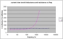
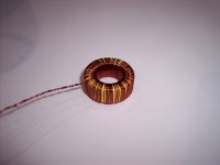
Made a first pass at the current viewing toroid. As I said, it is from an old ATX supply, I wound it fully with #26 magnet wire, it took 87 turns to fill the toroid bore.
Measured the inductance from 20 hz out to a meg, but 500 k and one meg didn't make the meter very happy, so I removed those data points.
Toroid OD is .90, ID is .55, thickness is .370, material unknown.
Has an inner clearance ID of .50 now, so rca's and wires bigger than that are out..
Here's the inductance and resistance plotted.. I left out the resistances above 50k to keep the scale. 50K was 8.8 ohms, 100K 27.3 ohms, 200K 110.3 ohms.
Next, I'm gonna stick a wire through it, measure the voltage produced with a scope, from 2 hz and 4 A peak, to 1Khz and whatever the supply can give...
Cheers, John
Attachments
megajocke said:Those yellow toroids are usually something similar to micrometals #26 iron powder material. They have pretty low permeability and high losses.
Ah thanks, I'll hafta do the equations to see the actual permeability.
Losses are interesting..luckily, I'm not going to push the core, as it's just low level signal application. The inductance meter was running about 10 milliamps.
I'm just happy that the thing was totally flat inductance wise across the audio band and out to 200 Khz...I'm working with some big iron laminated magnets, they drop 8.5% from 20 hz to 2 Khz. they have .5mm thick laminations.
Unbalanced for the time being. But I've designed the test apparatus to be useable for both.megajocke said:This looks like an interesting test. Are you interested in balanced or unbalanced interconnects?
I'm thinking of what it would take to put the sense toroid together with the drive toroid, and use it as a feedback for the drive. The intent would be to provide a constant current in the ground wires across the audio band, or maybe just a constant rate of change of flux, which would be a constant voltage output.
It may be easier to break it to constant current at lf, constant v at hf, that makes it easier on the drive supply.
Cheers, John
Are you trying yo use this as a current transformer? It won't work at low frequencies.
Magentizing inductance will steal most of the secondary current if it's impedance at the test frequency is not one order of magnitude higher than secondary resistance plus load resistance. Even when using flux cancellation (an inverting op-amp as a simulated short-circuit load), the required coupling capacitor and the magnet wire will still contribute with some resistance.
BTW: My latest project involves a custom electronic ground fault interrupter. I managed to do 60Hz sensing with a small 20Khz transformer.
Eva said:Are you trying yo use this as a current transformer? It won't work at low frequencies.
Magentizing inductance will steal most of the secondary current if it's impedance at the test frequency is not one order of magnitude higher than secondary resistance plus load resistance. Even when using flux cancellation (an inverting op-amp as a simulated short-circuit load), the required coupling capacitor and the magnet wire will still contribute with some resistance.
BTW: My latest project involves a custom electronic ground fault interrupter. I managed to do 60Hz sensing with a small 20Khz transformer.
Now ya tells me, eh??
Hi Eva, nice to hear from ya.
Ran a test..at 50 hz and 6 amperes peak. Output voltage into scope was 20 millivolts peak. A transfer of 3.33 mV per amp at 50hz..ran outta daylight today, I'll run a few more points tomorrow just to get an idea of how good or bad the toroid and coil really is... My plan is to compensate for rolloff of whatever I end up with, and not worry about phase.. I'll only drive sines, so taking data by hand and using a calc won't be too bad..
Unfortunately, I was not able to determine what the scope input z was set at..don't know if it was 50 ohms or 10meg. Gonna find me a 10x. Should clear that one up morrow also.
I've an old Hi-z preamp floating around somewhere, I'll find it..may have to modify it to go differential input, then shield the wires to the toroid.
What really troubles me is the output..noisy as all getout. HF hash. I didn't expect that of the Kepco.
I'll certainly have to limit the hf output of the toroid (strange word to edit?)...the kepco has switching noise on the output big time, it drove the scope nuts. I'm guessing my tiger 250 won't give me such hash.
3.3 microvolts per milliamp at 50 hz is too small for my taste..If need be, I'll go to a smaller guage wire. 49 is the lowest I have, but I will NOT try it, I can barely see it. I have rolls of stuff in between 26 and 49.
Cheers, John
stinius said:Could this thread be moved to the Solid State please?
Stinius
Sheesh, spoilsport...
Hey, I don't mind if it's what people want..
Cheers, John
- Status
- This old topic is closed. If you want to reopen this topic, contact a moderator using the "Report Post" button.
- Home
- Design & Build
- Parts
- Ground loops and containment