Well it'll give you a linear scale (rather than a logarithmic scale like we hear) loosely based on the peak level. You won't get anything until the input signal is greater than 0.6V because the 741 buffer can't bias the diode.
I'd turn the 741 into a precision rectifier and add x10 gain. If you want to get really fancy then Analog Devices has log amps/multipliers that could give you a dB scale.
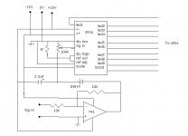
edit: whoops, something seriously wrong here. -ve of cap goes to +ve rail? If the LM3916 is -15V referenced then you'll always have the lower half LEDs on and only get display on the top half.
Cap should be ground referenced as should the LM3916 and providing a discharge for the cap is also necessary or it'll be a peak hold meter.
I'd turn the 741 into a precision rectifier and add x10 gain. If you want to get really fancy then Analog Devices has log amps/multipliers that could give you a dB scale.
edit: whoops, something seriously wrong here. -ve of cap goes to +ve rail? If the LM3916 is -15V referenced then you'll always have the lower half LEDs on and only get display on the top half.
Cap should be ground referenced as should the LM3916 and providing a discharge for the cap is also necessary or it'll be a peak hold meter.
edit: whoops, something seriously wrong here. -ve of cap goes to +ve rail? If the LM3916 is -15V referenced then you'll always have the lower half LEDs on and only get display on the top half.
Cap should be ground referenced as should the LM3916 and providing a discharge for the cap is also necessary or it'll be a peak hold meter. [/B][/QUOTE]
accidentally flipped the +/- on the supply rails, sorry bout that. the cap is tied to the neg rail.
Cap should be ground referenced as should the LM3916 and providing a discharge for the cap is also necessary or it'll be a peak hold meter. [/B][/QUOTE]
accidentally flipped the +/- on the supply rails, sorry bout that. the cap is tied to the neg rail.
an esoteric point but, there's no point waiting for the cap to charge from -V to 0V on start up - just reference it to 0V.
LM3916 vs 14 - hmmm, distance memories evoked. you could be right re. log scale. It's what the datasheet says....
Seeing as the 100K pot is the discharge path, the LM input impedance may reduce the discharge time at max gain (input impedance in parallel) your time constant is about 600ms so this things gonna dance pretty good.
got it working on the breadboard. the mods i tried on this circuit were first changed the gain to 10x in the 741 as Iain McNeill suggested, and trimming down the pot/divider accordingly. this resulted in the bottom 3 led's turning on in sequence as the sound came up instead of all coming on at once like before (when the 0.6V mark was crossed).
tying the cap to the ground rail produces unexpected effects as the led's seem to 'smear' when signal is applied (all glowing dimly but in sequence with the music). the led's also remain glowing very dimly with no signal applied. retying to -15V eliminated this.
as expected, higher values for c make the display a little more sluggish while low value ones make it faster and more smear like.
the 3916 runs very warm to the touch with all 10 led's lit, although im within spec according to the datasheet. think i should reduce led current? figure it will be rare when all 10 led's are all on for an extended period of time.
Sounds like the ground rail isn't really ground. There's going to be a significant current through the averaging cap and if this is running through the "ref_adj" or "div_low" pins rather than straight to PSU/741 then this noise injection will make LED jitter (for want of a better word)
Can you post a pic of the BB?
edit: and noise injection into the MODE pin modulates the LED brightness.
Can you post a pic of the BB?
edit: and noise injection into the MODE pin modulates the LED brightness.
I'm sure the LM3916 has a VU scale, which is really optimized for use as a tape recorder level monitor. One of the other two is a linear scale, and the other is log.
After reviewing a bunch of level displays in old magazines, about the nicest was in ETI, (reprinted in a best-of projects issue): it stacked a couple of displays for a wider range, did full-wave rectification and gave a simultaneous peak and average reading.
You can now buy a "dB display" made by "American Audio" that has a very wide range for about $60; only real drawback appears to be that it's all plastic, and I haven't found a vendor yet that doesn't charge an arm and a leg to ship to Canada.
I've traced the schematic and copied the layout of a level display that was used in a CM Labs CM920 power amp circa 1980; it used a bunch of comparators and a voltage divider to do 5 dB steps which covers a more useful range while using only 10 LEDs per channel.
- Status
- This old topic is closed. If you want to reopen this topic, contact a moderator using the "Report Post" button.
- Home
- Design & Build
- Parts
- please critique this level indicator