hi folks http://saint.419.removed.us/clapsw.html
i saw this site and followed everything and made that switch
but the result is diff
i clap to turn it on and it turns itself off in a short time ( i cannot clap to turn it off)
when it is off i can turn it on again but then
it turns itself off again in a short time
hmmmmm
it says it is a bistable circuit
but how come it cannot change states
please help
regards
Hi,
See you have had no replies") I looked at this circuit earlier and thought, erm, a classic textbook circuit that ain't gonna work.
I looked at this circuit earlier and thought, erm, a classic textbook circuit that ain't gonna work.
Not strictly true, it's a very basic circuit with potential problems despite it's simplicity.
What you need to do is verify the bistable operation. This relies on a very short "trigger pulse" from that 100nf cap.
What I would do is remove the BC547 mic amp, thats the left hand transistor. Solder a wire to the junction of the 5K6 resistor and the 100nf cap. Power the circuit up and very quickly touch the wire to the zero volt line (batt negative) . Doing this will "toggle" the bistable and it will alternately light, then turn off the lamp. A 100 ma bulb with a PP3 is no good either -- way to high a current draw. If you actually remove the lamp the circuit will still function using the LED's only, even with that leg of the transistor not connected at all. Try that for testing.
If it still doesn't work there is a construction error of some kind.
If it does work like this put the BC547 back and leave the bulb out still. The problem may be the triggering isn't "quick" enough.
If the collector volts of the BC547 amp ramps rather than switches the circuit won't toggle. Also if you had a bulb fitted the current draw may be so high the batt volts is falling to much.
Hope that helps.
See you have had no replies
I looked at this circuit earlier and thought, erm, a classic textbook circuit that ain't gonna work. Not strictly true, it's a very basic circuit with potential problems despite it's simplicity.
What you need to do is verify the bistable operation. This relies on a very short "trigger pulse" from that 100nf cap.
What I would do is remove the BC547 mic amp, thats the left hand transistor. Solder a wire to the junction of the 5K6 resistor and the 100nf cap. Power the circuit up and very quickly touch the wire to the zero volt line (batt negative) . Doing this will "toggle" the bistable and it will alternately light, then turn off the lamp. A 100 ma bulb with a PP3 is no good either -- way to high a current draw. If you actually remove the lamp the circuit will still function using the LED's only, even with that leg of the transistor not connected at all. Try that for testing.
If it still doesn't work there is a construction error of some kind.
If it does work like this put the BC547 back and leave the bulb out still. The problem may be the triggering isn't "quick" enough.
If the collector volts of the BC547 amp ramps rather than switches the circuit won't toggle. Also if you had a bulb fitted the current draw may be so high the batt volts is falling to much.
Hope that helps.
hi buddy
finally a hero came out and answered my question
ok
i tried to connect a wire to the junction of the 5.6k and the 100nf cap
and did what u asked me to
the lamp went on then went off very fast exactly like u said
i am sure nothing wrong with my parts or connections
coz i followed exactly what the circuit showed
but hmmmmmmmm
after i put back the bc547 transitor and removed the lamp
and replaced it with a led and a current limiting resistor
the result came out to be the same as i mentioned in my first thread
also u r right about the high current from the lampmy 9 v battery went dead very fast
still have no idea why i can only clap to turn it on but i cannot clap to turn it off
i have been waiting for a reply for 2 days
thanks so much pal
i will still try to figure it out again
i never give up even i am not good at electronics
ps: i even asked this in some other furums
some said maybe a transistor is open
hmmmm
i even checked every resistor with my tester
every part is working well
i not only checked those resistors
i even checked all in4141 and all 4 transistor connections
i mean every part and trace of it i have checked it over and over again like zillion times
regards
Put this together on a breadboard - it works but is oversensitive tends to switch at random - change the 100nf to a 10nf it responds better then.
I used what I had in the junk box (some to92 BC108's, IN4005's for diodes and an old cell phone microphone. the circuit seems tolerant of parts so I suspect you have a wiring problem - Change the 10microfarad microphone cap for sometthing similar - this may be leaky.
Good luck, you will get it working
Hi Spiny,
Your probably right about the 100nf. The secret is in getting the trigger pulse to have a fast risetime (or falltime more correctly).
If you are 100% happy that the bistable operation is correct ( it sounds to be ) then try, with it all wired up, measuring the voltage on the collector of the BC547 mic amp. Should be around 6 or 7 volts at a guess give or take. If it's sat at zero or very low this needs investigating. This part of the circuit is the weak point -- it's just to dependant on things like the gain of the transistor and the mic sensitivity.
To trigger the bistable the collector volts has to suddenly dip toward ground in response to the signal from the mic. The collector volts needs to be in the 6 or 7 volt zone meaning the transistor is "just" coming into conduction and any signal from the mic will just saturate it and bring the collector down to zero. Its not a linear amp, it's used as a crude switch.
Regards Karl
all appears to be there (this is the Component side?) . One tip to make mistakes less common, place the transistor pads so they are all fitted the same way round, less likelyhood of getting one in backwards  same for diodes and electrolytics.
and yes i know this is not always possible
same for diodes and electrolytics.and yes i know this is not always possible
hi guys
i finally made it work
reporting
i changed some parts
the amp input 10uf i changed it to a new 10uf cap i bought today
i changed the amp 4.7M to 47k(a guy said this value is too high so i changed it to 47 k and tried and it worked)
i also changed the bc547 emitter diode in4148 to in 4001
and i also changed that 100nf to 10 nf( the clap switch is now not as sensitive as it was- the first time it was too sensitive but now it is better)
all working fine now
thanks for all replies and teaching
regards

hi
thanks
the next thing i am going to make is a 5vdc power supply
i wanna use a transformer this time
since i just got a new one
it is a 220vAC primary and 9-0-9 secondary
20VA power transformer
some say the filter cap is like the bigger the better
but i saw some circuits
they only use 47u or 10u
i am going to use a 2200uf cap for the filtering
is it too much?
also i will use 7805 to get 5vdc
at the output of 7805
there is a filtering cap too but it is supposed to be a smaller one
also i will put a bypass cap 100nf parallel with the output cap
here is a circuit i found from the net
I do have a question about it
do you guys know why there is a 1k resistor at the output ?
what is used it for?
any suggestions , please kindly let me know
thanks
regards
thanks
the next thing i am going to make is a 5vdc power supply
i wanna use a transformer this time
since i just got a new one
it is a 220vAC primary and 9-0-9 secondary
20VA power transformer
some say the filter cap is like the bigger the better
but i saw some circuits
they only use 47u or 10u
i am going to use a 2200uf cap for the filtering
is it too much?
also i will use 7805 to get 5vdc
at the output of 7805
there is a filtering cap too but it is supposed to be a smaller one
also i will put a bypass cap 100nf parallel with the output cap
here is a circuit i found from the net
I do have a question about it
do you guys know why there is a 1k resistor at the output ?
what is used it for?
any suggestions , please kindly let me know
thanks
regards
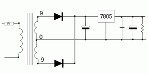
Attachments
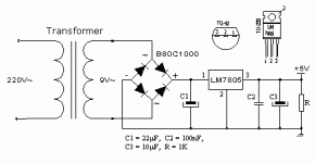
with a 9-0-9 secondary use a bi-phase rectifier for 5V - gif attached - as this will give a secondary rectified voltage of about 12v (9V *1.414 -0.7v diode drop). so the 7805 only has to drop 7V at your design current. You may and probably should use a heatsink on the 7805. You can calculate the heat produced by the voltage drop and the current passed, 1/2amp will give 3.5watts to dissapate for example. 
As to the final resistance, this is to provide a load when no circuit is attached. I usually connect a LED and resistor here as a power on indicator and to provide a load if the circuit is disconnected.
The capacitors will do, only a small one is needed on the output of the 7805 as the DC is regulated by the chip. Large input capacitors may need heavy duty diodes to cope with the surge, You may need a 3amp diode (1N5401 etc.) rather than a 1N4001 here.
Attachments
Hi,
your 20VA 9-0-9Vac transformer has a maximum continuous output of 20/[9+9]=1.1Aac.
If you use this to feed a capacitor input filter to get a +-12Vdc supply the maximum continuous output is approximately half the AC output i.e. ~550mAdc.
If you run the transformer at it's maximum rating of 550mA it will run hot, right up at the maximum that the manufacturer designed it for. This internal temperature will be about 130degC.
I suggest the maximum continuous demand be limited to about 50% of rating i.e. 280mAdc continuous.
hi folks
today i hooked up my power supply and tested
found out something diff from Andrew said
i used 9-0 of the secondary to connect a bridge rectifier and a filter cap
to get 12vdc for a portable tv and connect a current meter
in series of it
but the meter showed 0.7A
i even ran it for 2 hours ( the tv was working well for 2 hrs too)
and i touched the metal part of the power transformer
it was not very hot
i wonder why
Does anyone know why?
please kindly help me
Simon
- Status
- This old topic is closed. If you want to reopen this topic, contact a moderator using the "Report Post" button.
- Home
- Design & Build
- Parts
- a doubt about a circuit