hi all. just wondering if this circuit is OK for measuring hfe in transistors for beta-matching purposes. it seems to agree with what i know about electronics theory, just wanted to post it here to make sure there wasn't something i was missing or perhaps an easier way.
thank you.
thank you.
Attachments
http://www.diyaudio.com/forums/showthread.php?postid=1447106#post1447106
BTW,
search "match" & "anatech" report as posts and it's the 5th in a list of 233.
BTW,
search "match" & "anatech" report as posts and it's the 5th in a list of 233.
I'm searching for Anatech's diagram and am unable to locate it. I'm trying to match differential pair BPJ NPNs. Any help would be appreciated.
I read the circuit description and am puzzled by the description of the portion of the circuit controlling the bases. There is mention of base resistors to common ground but there must be more?
I read the circuit description and am puzzled by the description of the portion of the circuit controlling the bases. There is mention of base resistors to common ground but there must be more?
For NPN:
the LTP pair need +ve & zero & -ve
The two collector resistors go to +ve
The tail resistor, or CCS, goes to -ve
The two base resistors go to zero.
You can omit zero by using a resistor ladder/divider from +ve to -ve and tapping the base resistor to the junction. one or other leg of the divider can be a variable resistor.
I prefer to add a single resistor above the two collector resistors so that I can check the LTP TOTAL current. I can then adjust the base voltage and monitor the LTP current. A switchable CCS removes the need for this complication.
I set myself the task of finding out the gain of a whole load of unknown transistors back in the late 1970s.
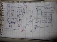
I came up with several fixed collector currants set by fixed resistors and two ranges of variable of base currant and measured the base currant with a meter.
I had to divide the collector currant by the base currant to get the Hfe.
It was a crude curve tracer and the only bit missing from the drawing is the NPN/PNP switch (a double pole change over switch connected where the red crosses are shown).
It is typical of a teenagers home brew junk box circuit and was still working last year when I used an external bench power supply to test with collector currants of up to 4 amps. The 10 volt regulator would never have coped with this huge demand
I could use it to make matched pairs including complimentary matched pairs
Attachments
Thanks Andrew and Refugee for the info. I used a simple circuit similar to refugees suggestion to measure the gain (hFE) using a 10ua base current. This was handy as it allowed me to quickly reject 15% that were outliers. The remaining fell within a tight distribution between 350 and 370. Much more consistent than I had expected.
The problem with this method was temperature dependency. If you pick up a handful you will skew the results as they warm in your hand. The longer they operate, the greater the reading. This effect was very significant and it was difficult to have much confidence in the results.
After Andrew posted his response and corrected my misunderstanding, I built a jig based on his circuit and retested pairs from my previously classified and parsed group of 85 transistors. I found that the initial test really didn't accomplish much, other than rejecting a few that fell far from the mean. Those retested from the previous classifications were probably no better than random selection. I've have been able to match a few pairs that act well together throughout the expected range but temperature dependency is still an issue.
I've found that by placing the transistors close enough to touch often yield a different result than moving them apart. It would stand to reason that attaching them together with some thermo paste would be an interesting experiment. I did that with a matched pair and once attached, they diverged widely. I can only assume they they were operating at different steady state temperatures even though they were passing the same current. Once attached they must have come to a common average temperature that forced them out of balance.
Once installed in the amplifier, I notice that the DC offset on power up is about 20mv. As the amp warms up and the devices come to equilibrium temperature, the offset drops to about 10mv. Touching one device or the other affects temperature and hFE enough to slew the DC offset, as one would expect.
Interesting stuff. Is anyone aware of a low noise matched differential pair device on a single form? That would seem to be a solution.
Last edited:
My target measurement was to get an absolute value for Hfe at a constant VCE. The temperature drift may be contributed to by the VCE changing as the currant rises and falls.
I just looked at the few data sheets that were to hand back in the late 1970s and took a shot at what they were showing and made the working circuit I still have today.
Those dual transistors were selected before the chips were cut from the die and only pairs that were side by side were sent for packaging in resin or metal cans.
They were mainly used in test instruments and the like.
If you want two thermally coupled resistors to track each other for temperature, then the Pq of both must be near identical.
To get that equality of Pq you need to set up the LTP, so that Vce and Ie are the same.
You must balance the LTP.
Then the two transistors will give out an offset that depends on the base currents and base resistances and base voltages. If you match the base resistances and match the hFE then the only variable that is left to create output offset of your correctly balanced LTP is Vbe. That Vbe matching is what you select when you match your input transistors.
- Status
- This old topic is closed. If you want to reopen this topic, contact a moderator using the "Report Post" button.
- Home
- Design & Build
- Parts
- measuring hfe / beta