An externally hosted image should be here but it was not working when we last tested it.
The welder is an inverter tig that has a three prong 240 plug. My shop has a three prong 240vac receptacle/service. I attached an image of the operating manual page that describes the power requirements.
(the image was too big to upload so here's a link)
http://img378.imageshack.us/img378/1605/jpegofmanualpageon5.jpg
Inside the welder the green/ground from the 240 service is bolted directly to the chassis. I'm taking 120 switched from one of the legs so that I can turn the cooler on/off with the welders main switch. The cooler I'm making is intended basically to be a semi attached 'auxilliary' unit to the welder.
I was afraid this was too elementary a question so I snuck out to an electrician and he told me it was 'electronic' and beyond his ken. But it was his opinion that I could just wire it as I've shown in the diagram and attach both neutral coming into the cooler AND ground from the SMPS to the cooler chassis.
I went to an electrical engineer at a plant down the street that manufactures transformers. He scratched his head for a while and admitted that he could not tell me anything certain.
I don't know whether to be astonished or demoralized. I asked half a dozen more people ranging from heating and cooling guys, electricians, and in other forums such as this. I got half a dozen more answers. Some said my only option was to rewire the service for a four blade plug and replace the line on my welder so that I had a separate ground and neutral going back to the service box (where they are, naturally, joined together anyway). Only then, it was stated, would I be able to connect my SMPS ground to chassis and true ground, and then the neutral would be 'floating'.
Is it really that complicated? I want to be safe. I don't want to damage the SMPS. I don't want to burn my house down. I put in my service and wired my entire home, including this shop. Had it inspected and the inspector praised my work.
So why does this stuff seem beyond my (and most others I've asked) comprehension?
The following was suggested. Can anyone elaborate on how this is actually implemented? Is it really the only way to go short of rewiring to a four prong outlet?
If you only have a three-prong plug, you must use a transformer with a primary of 240v, and go between L1 and L2. Otherwise, you will be putting current through the ground wire, and there will be voltage on the chassis.
Am I energizing the chassis however I choose to ground it the diagram I posted? So if what is stated is true, is my welder then utilizing an interal transformer of the type/application mentioned to keep the current from being put through the ground wire? (that doesn't make sense i know, but i'm just showing how frustrated/confused i am)
Although you could use the ground wire and a hot wire to provide 120V, this is NOT good practice, and would not conform to code, since the ground conductor is not to be used as a current-carrying conductor, it is there for fault protection only.
If the welder has 4-wire service (hot, neutral, hot, ground), go ahead and connect the SMPS to one hot and to neutral. The ground connection for the SMPS would obviously be connected to ground.
If the welder does not have a 4-wire service, you only really have two choices. Either get an SMPS that can operate on 240V, or a step-down transformer with 240V primary. Ground must still be connected to ground.
I'm trying to understand the idea that the ground is never to be used for current.
This is a brand new model welder from Thermadyne Worldwide. It uses three wires to connect at the receptacle to 240vac using two 120vac wires and a ground. Is it not using that ground inside the machine as the leg to make 120 plus 120 equal 240?
I looked into a comparable model from Miller Welding. This years Dynasty 200dx Inverter Tig connects to single phase 240vac in exactly the same manner. How is this machine constructed to a level of acceptable safety adequate to allow it to be sold anywhere in the United States, that I cannot achieve by using the same power source?
In 240V single-phase applications, current flows from one HOT wire to the other HOT wire. No current flows in the ground wire.
Some appliances use a neutral wire because they also require a 120V supply on top of the 240V. For example, an oven range might use 120V for the control circuitry and the 120V front panel outlets, a clothes dryer might use 120V for the motor.
The arc welder on the other hand might only need 240V supply to it's transformer, thus a neutral connection is not required.
If I'm understanding this correctly, you want to wire the 120v water cooler power supply directly to the 240v welder?
If so, you cant do that with what you have currently.
As you said, the equipment grounding conductor (green "ground" wire) must never carry any current.
The welder manual page you posted is specific about not using a neutral connection.
The person who told you you need to re-wire to a 4 wire receptacle was correct.
Alternately, you could connect the water cooler setup to a normal 120v receptacle with a standard 3 prong 120v house plug.
As an explination, the equipment grounding conductor, commonly referred to as ground, has only one function.
That function is to carry return current and pop a fuse/breaker in the event that a voltage carrying conductor (hot leg) shorts to exposed metal. (Or anything else other then the neutral conductor.)
This is what keeps you alive if something goes wrong.
This is also the reason the equipment grounding conductor is bonded to the neutral at the service enterance. To provide a current path for faults to ground back to the neutral to blow the fuse/breaker.
Current on the EGC (ground) gives I^2R losses along the conductor, locally elevating the voltage of the grounded equipment above all the other grounded equipment.
Touch this mis-wired piece of equipment, along with another piece of equipment not on the same outlet, and you may be killed.
Now I'm not a licensed electrician, however I do have the 2008 national electrical code sitting next to me, which I have read and mostly understand.
As such, I disclaim any and all responsability if your house burns down or you kill yourself.
Not that I remotely expect it to with the advice I have given you, but just in case.
-Edward
Current does NOT flow in the neutral conductor, if you look at another post on here titled 'How to connect gnd' in the Chip-AMp section and the thread was started by samsagaz. I have put a simple drawing (at/near the bottom of the thread) showing how electricity is generated (3 Phase) and you will see that the Neutral and Earth both come from the same point in the generating set, this is called the 'Star Point'
To prove that electricity does not flow in the neutral, AND PLEASE DO NOT TRY THIS AT HOME, when I install Single or Three Phase boards, when every circuit is switched on you can touch the Neutral bar with your finger and you will not get electrocuted. Again DO NOT TRY THIS AT HOME, as you cannot guarantee that you main supply is perfect. By the way some boards I install run at 250Amps @ 400v. Which is one hell of a lot of power and WILL KILL YOU.
If your welder needs 240v then you would need to step-up the supply voltage over in America from 120Vac to 240Vac using a Step-Up Transformer.
To switch both at the same time you will need an interlinked (not electrically but mechanically) double pole switch that is rated above 230v, get a 400v switch to ensure that the insulation does not break down, welders draw lots of power, and give them their own supply, one at 230 and the other at 120v. The double-pole interlinked switch does not (ever) switch your earth. An alternative to using this type of switch would be to use either relay or contactor switching. The contactor method is the safest and the one that I would go for, but really there are a number of ways to achieve what you are looking for.
Both Earth's, the one in the welder and the one in your cooler need to both be connected to supply earth for compliance with regulations.
Gareth (BS 7671 Qualified Electrician)
PS....Please, Please, Please do not fool around with mains electricity under the right conditions 30mA is enough to kill.
Again ELECTRICITY KILLS
I think you're thinking the wrong way about North-American household power distribution. Power to a household is supplied from 3 wires, two labeled as "hot" and 1 the "neutral". The neutral is actually the center-tap of the pole transformer, with the hot wires being each end of the winding. From the center-tap to either end the voltage is 120 volts. End to end (hot to hot) the voltage is 240V.
As such, power outlets and circuits can be wired as either 120V or 240V, or both (4 prongs). 120V circuits in breaker panels are set up in such a way that the load on each hot wire is more or less balanced. For 120V circuits, current flows through 1 hot wire and the neutral (center tap).
A typical household has a majority of 120V appliances, mostly low-powered. High-powered appliances such as oven ranges, hot water heaters, and space heaters operate on 240V.
I did realize after I posted that I'd misapprehended something. I had thought that the hot wires used the ground to complete. I measured across both hot wires and indeed got 240.
It looks like the avenue I'm seeking is to use a transformer off of the two hot legs (240) and step it down to 120v. Now I can use the ground to connect to the chassis of this project.
This presents a new challenge. I've spent a couple of months in the shop painstakingly paring off pounds and inches from this thing and it is now the size of a large brick. I have a space approx 4 x 2 x 2.5 inches left in it to accomplish transforming 240 to 120 for use by my switch mode power supply and a small electric pump.
Any recommendations? After all this work I hate like hell contemplating an 8 x 8 x 8 inch separate power supply. Even a stacked core transformer is going to set me way back in weight and bulk.
TheMG - I still need 120vac for my pump. I cannot at this point easily swap the motor for a 12vdc or 240vac motor. I need 12vdc for fans and panel meters so these cannot be substituted for 120 or 240v versions either. I'm stuck with mixed voltage needs and trying to work it out.
gareth - I'm trying to get my head around that idea. There are two 120v hot wires and one ground in this service to the welder that I'm trying to tap 120v from. I cannot safely use that ground to get 120 from either of those single legs since I'm compromising the use of that ground as a safety feature. Apparently I need to use the 240 available from across the two hot 120v wires, leaving the ground alone, and then transform that 240v down to 120v.
Are you suggesting that I can negotiate what I've just described with a suitable switch?
This is what I'm looking at now
An externally hosted image should be here but it was not working when we last tested it.
You seem to only be able to get live and earth from the welder so you can't just wire out from it... therefore!
1)You'll need to wire a neutral from a mains socket to the cooler, best way is to use a new mains cable that facilitates all the connections available from you sockets and take the necessary neutral from that.
2)Wire the switched live from the welder.
3)take the earth from welder earth.
Should work fine with just wires, unless you want to go the transformer route")
Please someone correct me if this is wrong... it seems to be what others are saying like Una.
Gareth, as i understand it current has to flow in the neutral wire ?? it may not necessarily develop much of a voltage but its still there.
1)You'll need to wire a neutral from a mains socket to the cooler, best way is to use a new mains cable that facilitates all the connections available from you sockets and take the necessary neutral from that.
2)Wire the switched live from the welder.
3)take the earth from welder earth.
Should work fine with just wires, unless you want to go the transformer route
Please someone correct me if this is wrong... it seems to be what others are saying like Una.
Gareth, as i understand it current has to flow in the neutral wire ?? it may not necessarily develop much of a voltage but its still there.
QUOTE]Originally posted by bluebeard
TheMG - I still need 120vac for my pump. I cannot at this point easily swap the motor for a 12vdc or 240vac motor. I need 12vdc for fans and panel meters so these cannot be substituted for 120 or 240v versions either. I'm stuck with mixed voltage needs and trying to work it out.
gareth - I'm trying to get my head around that idea. There are two 120v hot wires and one ground in this service to the welder that I'm trying to tap 120v from. I cannot safely use that ground to get 120 from either of those single legs since I'm compromising the use of that ground as a safety feature. Apparently I need to use the 240 available from across the two hot 120v wires, leaving the ground alone, and then transform that 240v down to 120v.
Are you suggesting that I can negotiate what I've just described with a suitable switch?
This is what I'm looking at now
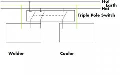
From what I understand, in America (the US?, how do I say?), you have the option of using either one or two of the hot wires for 120 or 240v respectively. The third is a combined neutral and earth.
Stop me if I misunderstand what you want to achieve...if you take the two hot's to the welder for 240v and obviously the combined neutral/earth then you will have the power to supply it, no?
Then to get 120v to the cooler just take a single hot and the combined neutral/earth for 120 and tap off the neutral for your earth, remember it is combined. In the UK we call PEN (Protective Earth and Neutral).
You can then use a triple-pole switch to switch the three hot wires to enable the power into both welder and cooler at the same time (this is what you want to do? switch the two on at the same time).
At a 30amp rating then you will need to use a 45amp triple pole isolator.
Have a look at the drawing below.
Gareth
TheMG - I still need 120vac for my pump. I cannot at this point easily swap the motor for a 12vdc or 240vac motor. I need 12vdc for fans and panel meters so these cannot be substituted for 120 or 240v versions either. I'm stuck with mixed voltage needs and trying to work it out.
gareth - I'm trying to get my head around that idea. There are two 120v hot wires and one ground in this service to the welder that I'm trying to tap 120v from. I cannot safely use that ground to get 120 from either of those single legs since I'm compromising the use of that ground as a safety feature. Apparently I need to use the 240 available from across the two hot 120v wires, leaving the ground alone, and then transform that 240v down to 120v.
Are you suggesting that I can negotiate what I've just described with a suitable switch?
This is what I'm looking at now
An externally hosted image should be here but it was not working when we last tested it.
[/QUOTE]From what I understand, in America (the US?, how do I say?), you have the option of using either one or two of the hot wires for 120 or 240v respectively. The third is a combined neutral and earth.
Stop me if I misunderstand what you want to achieve...if you take the two hot's to the welder for 240v and obviously the combined neutral/earth then you will have the power to supply it, no?
Then to get 120v to the cooler just take a single hot and the combined neutral/earth for 120 and tap off the neutral for your earth, remember it is combined. In the UK we call PEN (Protective Earth and Neutral).
You can then use a triple-pole switch to switch the three hot wires to enable the power into both welder and cooler at the same time (this is what you want to do? switch the two on at the same time).
At a 30amp rating then you will need to use a 45amp triple pole isolator.
Have a look at the drawing below.
Gareth
Attachments
bluebeard said:I did realize after I posted that I'd misapprehended something. I had thought that the hot wires used the ground to complete. I measured across both hot wires and indeed got 240.
It looks like the avenue I'm seeking is to use a transformer off of the two hot legs (240) and step it down to 120v. Now I can use the ground to connect to the chassis of this project.
This presents a new challenge. I've spent a couple of months in the shop painstakingly paring off pounds and inches from this thing and it is now the size of a large brick. I have a space approx 4 x 2 x 2.5 inches left in it to accomplish transforming 240 to 120 for use by my switch mode power supply and a small electric pump.
Any recommendations? After all this work I hate like hell contemplating an 8 x 8 x 8 inch separate power supply. Even a stacked core transformer is going to set me way back in weight and bulk.
How many amps do you need, from the 120vac?
You can check for transformers at places like http://www.mouser.com , http://www.alliedelec.com , and http://www.digikey.com , among others. The Hammond Manufacturing website is at http://www.hammondmfg.com .
Looking at the Mouser catalog, there at least ARE some transformers that will give you 115v from 230v, that are small-enough. But whether or not there is a suitable model will depend mostly on how much power you need. For example, the Hammond 185E230 could give you 115v@0.7A (80 VA), if you wired the secondaries in parallel, and measures 2.5" x 2.37" x 3.0", although the 2.37" includes the flat mounting tabs, which are wider than the rest of the transformer. I also noticed that there are some Triad models that might work, depending, again, on your power requirement, such as mouser.com part # 553-N1X (50 VA, 0.435A@115v, 2.281 x 3.688 x 2.000), and 553-N2X (100 VA, 0.87A@115v, 2.625 x 4.000 x 2.063).
Good luck.
gareth, you are misapprehending the same thing i did originally. I believe I understand wiring well enough, but I'm going to have to go back to the texts again to see how a service performs the feat of providing 240 across the two hot 120 lines without making use of the ground! You even state if you take the two hot's to the welder for 240v and obviously the combined neutral/earth using the word obviously . I thought that was obvious as well but it is not. In your diagram I would be using the ground to complete a 120v circuit at the cooler and that is what I must avoid.
The two 120v lines at the plug provide 240 across them. The ground remains neutral, so to speak. I need to leave it that way.
The two 120v lines at the plug provide 240 across them. The ground remains neutral, so to speak. I need to leave it that way.
Gootee
I need approx 500 watts in any transformer.
I'm using about a three amp 120v fan motor to run the pump head and also using a 120vac/12vdc smps to run muffin fans and assorted other stuff not exceeding 1.5 amps total.
What is the smallest package I'm likely to find to get 500w?
I need approx 500 watts in any transformer.
I'm using about a three amp 120v fan motor to run the pump head and also using a 120vac/12vdc smps to run muffin fans and assorted other stuff not exceeding 1.5 amps total.
What is the smallest package I'm likely to find to get 500w?
The way I understand things for domestic single phase wiring here, the ground and neutral tie together at the breaker box- think of it as a single point ground that also ties to a ground rod outside. Now, you get 240VAC between the two hot lines, and no return is needed- just like a center tapped transformer where you don't use the center tap. You also get 120VAC from either hot line, to the ground or neutral wire. That's like using the center tap. The only caveat is you're not allowed to use a wire intended for ground, as a neutral, even though they're functionally the same thing, i.e., are connected to the same place. Since you have three wires- hot, hot, and safety ground, you don't have a legal way to do 120VAC. You can use a 240 to 120 transformer as mentioned, or you can run more wire so you have both neutral and safety ground.
bluebeard said:gareth, you are misapprehending the same thing i did originally. I believe I understand wiring well enough, but I'm going to have to go back to the texts again to see how a service performs the feat of providing 240 across the two hot 120 lines without making use of the ground! You even state if you take the two hot's to the welder for 240v and obviously the combined neutral/earth using the word obviously . I thought that was obvious as well but it is not. In your diagram I would be using the ground to complete a 120v circuit at the cooler and that is what I must avoid.
The two 120v lines at the plug provide 240 across them. The ground remains neutral, so to speak. I need to leave it that way.
If I sounded condescending when I said obviously then I apologise as I did not intend to come across that way.
So what you will need to do is to bring a neutral from your main incoming supply board (not sure what you call it over there). Then use the earth as normal.
I am not sure what sort of distance from your main incoming supply board you intend to rig up this system so I do not know exactly how many (cable) cores you need to bring to your rig. Perhaps you could let me know.
The switching can remain the same as what is in the diagram that I posted if you want everything to switch at the same time. Again, depending on where you are using this setup (in relation) to your main supply then there are a number of ways the switching can be done. What I drew in the diagram was assuming you need local isolation (control).
I take it that you will be using this at home?
Gareth
PS...240v from the two wires??...when one side swings to +120Vac then the other will be at -120Vac and at 'ground' in relation to the +120. In certain situations of supply, when no neutral can be 'found' you can use two phases to provide supply as each of the three phases are 120 degrees apart and there will always be a phase that is negative in relation to another. (I hope you understand!)
- Status
- This old topic is closed. If you want to reopen this topic, contact a moderator using the "Report Post" button.
- Home
- Design & Build
- Parts
- How do I ground this project?