
I suppose that'll work...but you can do better with a true full-wave voltage doubler. You can even use a bridge rect. here, though half the diodes act in parallel (IIRC), so it's less effective. (This strategy is used in dual-voltage switching supplies, where a switch or jumper changes it from FWB to FWD mode. Yep, the primary circuits have 340VDC on them!)
Anywho - it's basically two half-wave rectifiers pointing in opposite directions. One end of the transformer feeds a 'CT' between the two main filter caps, the other end feeds diodes which pump the caps alternately. This is known as a full-wave doubler because the ripple output is 120Hz, due to the stacked nature of the circuit.
I'll grab a circuit in a second...
Tim
grataku said:Bricolo,
no one has asked what do you intend to do with this...
Clearly voltage doublers are not the optimal solution if you care about ripple, otherwise why bother with the two secondaries, right?")
It's too hard to wait for the transformer I ordered
I want to test my gainclone with the spare parts I've got
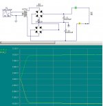
Definitely won't work. Transformer is s/c by upper bridge top left diode in series with lower bridge bottom right diode. Sorry to be a party pooper.mermoz said:try this:

Bricolo, Circlotron
I apologise for this hasting post ! sorry Bricolo !
I will learn to use sim tools a bit (a lot of bits !) better and will improve my electrical understanding skill, before replying to other similar posts
Definitely won't work. Transformer is s/c by upper bridge top left diode in series with lower bridge bottom right diode. Sorry to be a party pooper.
I apologise for this hasting post ! sorry Bricolo !
I will learn to use sim tools a bit (a lot of bits !) better and will improve my electrical understanding skill, before replying to other similar posts
Bricolo said:
It's too hard to wait for the transformer I ordered
I want to test my gainclone with the spare parts I've got
Hi,
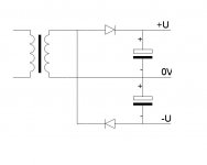
Rudys schematic is OK. This is half wave rectifier. I use them. Caps must be bigger, 4700uF or 10000uF for little ripple. Note; ground (0V) is connected to connection between caps (upper - and lower +)
Regards
zzeenn
- Status
- This old topic is closed. If you want to reopen this topic, contact a moderator using the "Report Post" button.
- Home
- Design & Build
- Parts
- Symmetrical supply rails with a 2 wire transformer, is it possible?