Hi,
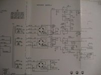
For some time ago I received an older function generator (Wavetek 191) which was not working properly. When powered, the output of every one of the output connectors (pulse sync out, sync out, pulse/square out, func out) goes to approx. +5 volts, and stays there no matter what buttons you press or what knobs you turn. I suggested that the problem was with the power supply. That was indeed the case, the attachment shows the power supply schematic (photograph taken from the original manual), and the voltage of the -5 V rail is about -0.8 volts. All the other voltages are ok.
The first thing I did was changing the caps C9 and C12, since this generator was built in 1983 (the same year I was born") ). That didn't help, so I changed the regulator VR4. Even that didn't help. It's not the front panel indicator lamp either (I removed it to test whether it was pulling the voltage to zero). And because the secondary voltages of the main transformer relating to +/- 5 volt regulators are just fine, the only thing that can be defective is the diode bridge CR2.
). That didn't help, so I changed the regulator VR4. Even that didn't help. It's not the front panel indicator lamp either (I removed it to test whether it was pulling the voltage to zero). And because the secondary voltages of the main transformer relating to +/- 5 volt regulators are just fine, the only thing that can be defective is the diode bridge CR2.
Does this make any sense? So far I have considered diode bridges to be virtually indestructible (considering the voltage and current stresses with this application). Can you see anything from the schematic that could be the source of this problem?
Scope shows that the input voltage of the -5V reg. is not that -11.3 V as it should be, but about -3 V instead of that. And, the voltage at the input terminal of the +5 V reg. is completely fine. I'm running out of ideas. This shouldn't be too complicated, right?
Thanks so much for your help!
p.s. One of the reasons I'm writing to this forum is to improve my written english - please be patient with my language-relating errors.
For some time ago I received an older function generator (Wavetek 191) which was not working properly. When powered, the output of every one of the output connectors (pulse sync out, sync out, pulse/square out, func out) goes to approx. +5 volts, and stays there no matter what buttons you press or what knobs you turn. I suggested that the problem was with the power supply. That was indeed the case, the attachment shows the power supply schematic (photograph taken from the original manual), and the voltage of the -5 V rail is about -0.8 volts. All the other voltages are ok.
The first thing I did was changing the caps C9 and C12, since this generator was built in 1983 (the same year I was born
). That didn't help, so I changed the regulator VR4. Even that didn't help. It's not the front panel indicator lamp either (I removed it to test whether it was pulling the voltage to zero). And because the secondary voltages of the main transformer relating to +/- 5 volt regulators are just fine, the only thing that can be defective is the diode bridge CR2.Does this make any sense? So far I have considered diode bridges to be virtually indestructible (considering the voltage and current stresses with this application). Can you see anything from the schematic that could be the source of this problem?
Scope shows that the input voltage of the -5V reg. is not that -11.3 V as it should be, but about -3 V instead of that. And, the voltage at the input terminal of the +5 V reg. is completely fine. I'm running out of ideas. This shouldn't be too complicated, right?
Thanks so much for your help!
p.s. One of the reasons I'm writing to this forum is to improve my written english - please be patient with my language-relating errors.
Attachments
Hi Bootstrapper,
Your English is quite good. I will try to do as well as you have done.
You are lucky to have the original manual for the Wavetek 191 (or to have any manual at all). That should be a nice unit to have, once it is working.
In equipment that is that old (well, that one is 'borderline'), if there is a problem with the power supply, I tend to just go ahead and replace all of the electrolytic capacitors in the power supply, just because of their age, while I've got the unit open and on the bench. If there are some needed capacitors that I don't have on hand, I might decide that those don't need to be replaced, yet. But I at least test their ESR (Equivalent Series Resistance), to feel better about it. ;-)
If you don't have an ESR meter, you might be able to use something like this: http://www.fullnet.com/~tomg/esrscope.htm . You will probably have to compare the readings to those of similar, known-good capacitors, until you 'get a feel for it'.
Also, be suspicious of any dipped tantalum capacitors, and any very small tubular glass capacitors. I have seen too many problems with those last two, in Tektronix equipment of about the same age. So I thought that I should mention them.
Power diodes and diode bridges do fail, occasionally. If you have narrowed it down to that, then you might as well remove it and test it out-of-circuit, at least, especially if you have something with which to replace it. Or, simply replace it and see if there is any change.
Good luck! Please let us know how it goes.
Your English is quite good. I will try to do as well as you have done.
You are lucky to have the original manual for the Wavetek 191 (or to have any manual at all). That should be a nice unit to have, once it is working.
In equipment that is that old (well, that one is 'borderline'), if there is a problem with the power supply, I tend to just go ahead and replace all of the electrolytic capacitors in the power supply, just because of their age, while I've got the unit open and on the bench. If there are some needed capacitors that I don't have on hand, I might decide that those don't need to be replaced, yet.
But I at least test their ESR (Equivalent Series Resistance), to feel better about it. ;-)If you don't have an ESR meter, you might be able to use something like this: http://www.fullnet.com/~tomg/esrscope.htm . You will probably have to compare the readings to those of similar, known-good capacitors, until you 'get a feel for it'.
Also, be suspicious of any dipped tantalum capacitors, and any very small tubular glass capacitors. I have seen too many problems with those last two, in Tektronix equipment of about the same age. So I thought that I should mention them.
Power diodes and diode bridges do fail, occasionally. If you have narrowed it down to that, then you might as well remove it and test it out-of-circuit, at least, especially if you have something with which to replace it. Or, simply replace it and see if there is any change.
Good luck! Please let us know how it goes.
Thanks for replying!
I did not mention it earlier, but the -5 V supply feeds quite a large amount of different devices, each with their own bypass caps. So in order to find a defective capacitor, I should go through every one of them! And believe me, there are tens of them.
Yes, I would definetely disconnect the -5 supply from its load if I could. But there's no any circuit breakers, just copper traces - which I'd not like to break.
I guess I'll start from the diode bridge (as soon as I get some solder wick) and if that won't work, then I'll cut the trace and see if anything changes.
Thanks for helping, I'll post here when I've made some progress!
Bootstrapper said:Thanks for replying!
I did not mention it earlier, but the -5 V supply feeds quite a large amount of different devices, each with their own bypass caps. So in order to find a defective capacitor, I should go through every one of them! And believe me, there are tens of them.
Yes, I would definetely disconnect the -5 supply from its load if I could. But there's no any circuit breakers, just copper traces - which I'd not like to break.
I guess I'll start from the diode bridge (as soon as I get some solder wick) and if that won't work, then I'll cut the trace and see if anything changes.
Thanks for helping, I'll post here when I've made some progress!
Tektronix usually placed zero-Ohm resistors in series with each supply rail. It's unfortunate that Wavetek didn't do the same thing.
I would probably cut the trace, since that would be a valuable test. And it should be easier to cut and later re-bridge the PCB trace than it would be to remove and replace the rectifier bridge.
- Status
- This old topic is closed. If you want to reopen this topic, contact a moderator using the "Report Post" button.