Hi everyone--
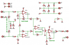
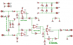
I'm trying to design a balance mic preamp circuit for myself, and I need some feedback on a couple of different options for the last stage which is going to drive the line-in of my sound card.
In the first one, the drive stage has fixed gain, which I moderate with an attenuator. The second one uses a pot in the feedback to adjust gain.
Another question I have is regarding noise. Is it better to have more gain early?
Right now I have the circuit drawn with OPA2134. I've been considering OPA2228 or perhaps LM4562. Can anyone recommend any other good, low-noise opamps for a design like this?
Also, I haven't started the PCB layout yet, and I don't really have any experience with high-gain circuits like this...any tips or tricks on the layout side?
Thanks for everyone's help--
Greg
Attachments
I have never designed one, but these guys have...
http://www.prodigy-pro.com/forum/viewtopic.php?t=16909
http://www.prodigy-pro.com/forum/viewtopic.php?t=16909
Gordy said:I have never designed one, but these guys have...
http://www.prodigy-pro.com/forum/viewtopic.php?t=16909
Holy **** that's a lot of info!!! How did I not find that one while I was searching? It's gonna take me weeks to go through it all.
While I'm reading...anybody out there care to comment on which of my 2 options is a better choice, and if the gain structure is OK? I've forgotten what little I learned about noise analysis.
This thing is going to be battery powered with 9.6V NiMH batteries, 4 in total. 2 for phantom power, and 2 for the opamp supplies.
--Greg
You know you can get pretty much that whole curcuit in an IC (Ballanced Differential input and unballanced output) useing a THAT1510 or a INA217 and it will have lower noise and the Gain can be set with either a fixed/switched resistor or a Gain pot...It would save money as these Chips are less that $5 each and it will save in PCB size...I have built Basic Mic preamps with these Chips that were less than 2in Square and totally quiet and have a Max gain of 66db (72db if you add a ballanced line driver or Output transformer)......
Cheers
Cheers
Minion said:You know you can get pretty much that whole curcuit in an IC (Ballanced Differential input and unballanced output) useing a THAT1510 or a INA217....
Yeah, I know about those chips. I've got a design using the INA127 on the drawing board as well.
This is as much about learning for me as it is anything else. So I need to go down the "wrong way" path and see where it takes me.
Wrong Way #1 (unpublished): 100K/20K feedback resistors and a TL072 with 47dB of gain makes for a poor mic preamp.
--Greg
I bet that the TL072 pre amp could be made a lot better with an impedance matching transformer, but that's a $100 option for a good one....
Is there some reason you want 18v phantom power? - seems to me you could stack the batteries and at least get 36v without trouble.
-tINY
tINY said:Is there some reason you want 18v phantom power? - seems to me you could stack the batteries and at least get 36v without trouble.
Since I'm using 9V batteries, that's 2 for phantom power and 2 for the opamp supplies. Something in the back of my head is telling me I can't hang the mic power across the +9 and -9 rails without bad things happening. Am I wrong?
Aside from a lower Max SPL capability, what's the downside of a lower phantom supply? From doing some reading, I realize that the 6k8 resistors should be reduced to something like 1k2.
If I *can* hang the phantom supply across the +9 and -9, then I can use only 2 batteries total instead of 4.
--Greg
gmikol said:
Aside from a lower Max SPL capability, what's the downside of a lower phantom supply? From doing some reading, I realize that the 6k8 resistors should be reduced to something like 1k2.
--Greg
Depends on the mic. Not all mic preamps are happy with funny voltages, some may simply move outside there normal bias points and be grossly distorted - for example, if it is a valve mic, bad stuff may happen unless it gets the expected 48V.
I cannot see any harm in stacking the phantom voltage on top of your +9V rail, which would get you up to 27ish volts.
Well...Its an ECM8000. This preamp is going to be primarily for measurement. It's spec'd at +15 to +48, so I would have to imagine that +18 will be OK. I'll probably add some sort of indicator to show low battery so I know when to recharge them.
I hadn't thought of just stacking it off the +9 to get more voltage. It keeps the ground reference intact.
I'm starting to have a feeling I'm going to have a lot of jumpers on the next version of my PCB to test various configuration options.
--Greg
I hadn't thought of just stacking it off the +9 to get more voltage. It keeps the ground reference intact.
I'm starting to have a feeling I'm going to have a lot of jumpers on the next version of my PCB to test various configuration options.
--Greg
- Status
- This old topic is closed. If you want to reopen this topic, contact a moderator using the "Report Post" button.
- Home
- Design & Build
- Parts
- Opinions on Mic Pre-Amp circuit