Hello all.
I have bought this module from Velleman
http://www.velleman.be/ot/en/product/view/?id=19215
to use as a car voltmeter.
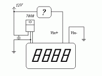
I am using a 7808 voltage regulator IC to keep the main voltage in the manufacturer specs.
My problem is: if I directly connect the module inputs to 12V (assuming VCC is 12V), the module will simply go bonkers, not displaying anything except some lit up segments.
If I connect the inputs to another voltage source, it will display correctly the voltage.
I've attached a schematic of the circuit. Basically, what should I place in the [?] box to cure this problem, as the voltage to be measured in the car will be the same as the supply voltage.
Thank you very much for your help
Attachments
1. The 7808 will like an output filter cap to prevent oscillations, anywhere from 4.7uF to 100uF electrolytic.
2. There is a lot of noise on a car 12V line, try 100 Ohms in series with the module sense lead and a .1uF to local ground. Verify that the input resistance of the 100 Ohms doesn't make the meter read low with a second DVM.
3. The 7808 might not last, I've seen spikes from the starter motor of over 50V when the start relay de-energizes I think the 7808 is limited to 35V input.
Do you have any more information on this meter? The webpage you linked to is really lacking in details. It says the input sens. is 200mV FS, which I would take to mean it measures from 0-200mV, but then it says it's 3.5 digit and doesn't tell you how the measurement is scaled for display. I guess that 200mV input reads as 1999 on the display. It mentions that you can place a decimal point wherever you want. So in other words, each count represents ~100uV.
You will need a resistor divider network in your '?' box to scale the input voltage to the 0-200mV input requirement. For example, if you're trying to read the operating voltage of the car's electrical system, a range from 0-19.99V is reasonable. You would need to divide the input by a factor of 100. Use resistors like 1K and 100K in your divider. Then place the jumper so the decimal is in the second position, and you're set.
You will need a resistor divider network in your '?' box to scale the input voltage to the 0-200mV input requirement. For example, if you're trying to read the operating voltage of the car's electrical system, a range from 0-19.99V is reasonable. You would need to divide the input by a factor of 100. Use resistors like 1K and 100K in your divider. Then place the jumper so the decimal is in the second position, and you're set.
Are you saying that powering the meter in your car from a 7808 causes the device to go bonkers? It shouldn't be too difficult to get any electronics working in a car...it's a nasty environment but it's not an unsolvable problem. There are tons of sensitive electronic devices in a modern car, and they all work fine.Simpleton said:The module itself already has precision resistors that form a divider network so it can read 0-20V.
Seems like a 9V battery is the only way to go
Thank you for your advices, I really appreciate them
Some things you might try:
- more supply decoupling. power in a car is dirty, more decoupling will help smooth out any sags. before the regulator is probably more effective.
- a low-pass on the measurement lead. add a capacitor across the meter reading pins to smooth fast transients on the measured voltage
- an inductor (choke, coil) in series with the power supply will help smooth any spikes. place it before the regulator.
- a zener diode, reverse biased from the input to ground, maybe a 16-20V unit will help conduct any high voltage spikes to ground and protect the circuit from voltages that aren't in its SOA, but I don't think they'll solve this problem. you could use one on both the power supply and measurement leads.
- Status
- This old topic is closed. If you want to reopen this topic, contact a moderator using the "Report Post" button.

