Hi everybody,
I have a problem. I need to remote control the volume in a tube based system, but I'm quite struggling with it.
I have tried to make a binary controlled relay network, but it was not good enough. (http://www.diyaudio.com/forums/showthread.php?s=&threadid=115006)
Now I want to go back to the basics and make a shunt attenuator on rotary switch. I was thinking about to make it with relays, but now I do not like relays at all and also I do not like the idea of the large pcb for at least 24 relays.
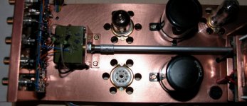
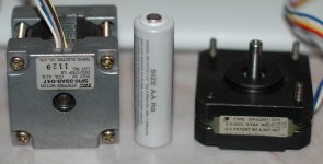
At the moment I use a black alps, which is turned by the smaller stepper motor (same type, from an old floppy drive) on the right side.
I have tried to make a control for the switch. First I have tried if the motor on the left side has enough torque or not, it has plenty. It turns it with half current.
Than I made a little program to step 8 step (about one position) and release. It does not work. The reason is, when I release the motor or turn the swith by hand it is left in an unknown step phase. When start to turn it starts sometimes backward and step a few in the right direction. This is because the motor is not in the position what the uC think.
Now I'm stuck here. I do not want any attenuator IC, not even relay, but stay with the rotary switch, but I have to solve the mechanical problem somehow. I'm looking for any suggestion.
Thanks,
JG
I have a problem. I need to remote control the volume in a tube based system, but I'm quite struggling with it.
I have tried to make a binary controlled relay network, but it was not good enough. (http://www.diyaudio.com/forums/showthread.php?s=&threadid=115006)
Now I want to go back to the basics and make a shunt attenuator on rotary switch. I was thinking about to make it with relays, but now I do not like relays at all and also I do not like the idea of the large pcb for at least 24 relays.
At the moment I use a black alps, which is turned by the smaller stepper motor (same type, from an old floppy drive) on the right side.
I have tried to make a control for the switch. First I have tried if the motor on the left side has enough torque or not, it has plenty. It turns it with half current.
Than I made a little program to step 8 step (about one position) and release. It does not work. The reason is, when I release the motor or turn the swith by hand it is left in an unknown step phase. When start to turn it starts sometimes backward and step a few in the right direction. This is because the motor is not in the position what the uC think.
Now I'm stuck here. I do not want any attenuator IC, not even relay, but stay with the rotary switch, but I have to solve the mechanical problem somehow. I'm looking for any suggestion.
Thanks,
JG
Attachments
of course it must get a separate PSU.
I had already some experiment with uC on tube elctronics. I have tried to shield it once, but I found the best solution is to send it to sleep when not needed. An interrupt from buttons or IR receiver wakes it up when needed, it takes less than a second to action it than it sleeps again.
Bottom line, when I listen to music, it is FULLY static. I do not use LCD display, or multiplexing of LEDs. As soon as it sleeps, there is no oscillator running, no signals changes going anywhere. If the PSU is not overloaded (would be hard to overload with a few LEDs and the few uA of the controller), this is not recognizeable in the sound. I know many tube funs will say proximity of a digital device disturbe the sound, but this is the way how to avoid.
Regards,
JG
It is an option to know the home position, do not use the aretation of the switch at all, position with the stepper, but than I can not control it directly by hand.
Most likely this is the solution, I will build the wafers on the stepper, the small is enough than all I need is an accuratre home position detection.
If I can, I still want to rather add it as a feature, so I handle the rotary switch rod directly, but a motor can turn it also (when our 10month old baby got sleep in my arms, this all is for this mainly, I'm not that lazy")
... or, I just use a long rod from the armchair
Regards,
JG
Most likely this is the solution, I will build the wafers on the stepper, the small is enough than all I need is an accuratre home position detection.
If I can, I still want to rather add it as a feature, so I handle the rotary switch rod directly, but a motor can turn it also (when our 10month old baby got sleep in my arms, this all is for this mainly, I'm not that lazy
... or, I just use a long rod from the armchair
Regards,
JG
This will solve your problem (i hope).
http://eshop.diyclub.biz/product_info.php?products_id=195
MV-01 complete volume remote control with ALPS motorized
pot ,for 35$ and 20$ shipping cost to Greece. (i think shipping
cost to Hugary will be the same )
Also http://eshop.diyclub.biz/product_info.php?products_id=247)
MV-06 for 39.15$
Let me know if my reply helped you.
Thanks, I have already a solution to control a black alps, but that is not strong enough for a rotary switch + there is a problem with positioning.
My problem is, my new amp (2A3 PSE) shows the quality of the black alps clearly, so I want to upgrade to resistor ladder on rotary switch. With a transistor based amp it helped to hide some sharpness.
(In the other hand, my dougter is 11month old now, she gets sleep other wasy more and more, not in my arms listening to Loreena McKennitt any more, so soon I will not need it much
Regards,
JG
Make sure the motor steps are of angles equal to, or divisible by the rotary switches step angles. Example rotary switch steps are 15degrees. Then the stepper motors steps must be 15, 5, 1, ect. degree incraments.
Someone above also had a good point
Add an extra pole to the rotary switch and use it as a feedback mechanism. This approch would probably work good with a non-stepper motor as well.
Someone above also had a good point
You could use the actual switch to detect positions
Add an extra pole to the rotary switch and use it as a feedback mechanism. This approch would probably work good with a non-stepper motor as well.
A found a thing I have never heard of : stepping solenoid. Looks like exactly what I want. The only problem is, they do not even respond to my emails. Two weeks ago I have called them and resend an email I sent before, but still nothing.
Have you heard of this ?
Thanks,
JG
Have you heard of this ?
Thanks,
JG
Jeb-D., I have tried, but I did not found it accurate enough. Even with a constant number of steps after making the contact does not provide near same position. I have tried to make a prototype in the meantime with a disc with small holes for light gate, hand made disc but immediately far better. The 0.5mm hole provide very tight control.
the DC motor does not work if you wnat to handle it by hand also, because of the gears. You need to use the DC motor with gears, but the stepper can connect 1:1, and not really recognizeable when de-energized.
I have two ways now, the control disc or the stepping solenoid. The second one would be perfect (if not too noisy).
Regards,
JG
I forgot to put the link in :
http://www.nsfcontrols.co.uk/pdf/solenoids/stepping/50LSteppers.pdf
http://www.nsfcontrols.co.uk/pdf/solenoids/stepping/50LSteppers.pdf
Eva said:Why going through so much trouble when even the lowest cost volume control IC in the market is probably more linear and quieter than the best tubes and output transformers ever built? I'll never understand.
Or, it could even be easily and cheaply done, probably with better performance than a switched attenuator (and no moving parts), with LED & photocell combos used as voltage-controlled resistances for an attenuator, with something like a 0v to 5v control voltage to take it from min to max attenuation.
There are commercial 'analog optoisolator' parts that have the LED & photocell encapsulated together, in a light-tight package, such as the Perkin-Elmer Vactrols (e.g. VTL5C2 and VTL5C3) and some of Silonex's stuff (e.g. NSL-32SR2 and NSL-32SR3).
For an example: Diyaudio's GeorgeHiFi uses two of the Silonex NSL-32SR2S parts for each channel, in a series/shunt configuration, in his Lightspeed Attenuator (see the 'Lightspeed...' thread, here at diyaudio.com), which seems to get rave reviews.
It would be trivial to make it voltage-controlled (i.e. with an inverting level-shifting differential amp (one opamp) to give 5v to 0v for a 0v to 5v input, to drive the attenuator's series resistance's current-control with 5 to 0v while the attenuator's shunt resistance's current-control got 0 to 5v).
For a tube amp, you might need to use a different optoisolator part (for a different resistance range than the Lightspeed uses, to get acceptable input impedance for tube amp's output).
Attachments
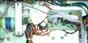
Looks good, however, I have tried to put 2 wafers directly on a 5.25" floppy drive head positioner motor and it works fine. the resolution is enough, no gear is needed, for this little bigger motor.
The problem is, I want to handle it by hand also. I do not like the idea of having an encoder at the front panel which drives the wafers by wire.
I try to make a better disc with holes for finding positon. I have an idea how :
I fix the switch on the base of the stand drill with vertical rod. I assemble the disc on the rod of the switch, drill a hole. Turn the swith with one position, than turn a hole again ........ 23 times. This way it should be more accurate.
Regards,
JG
Eva, linearity and noise is not my primary target, but I do not really want to open this tubes vs. solid stage etc. discussion here. Bottom line is, I do non wnat to see them on my audio chain nor most people I know who loves to listen to music.
I do respect them, they are fine for most application.
A year ago I was happy with my black alps, but recently I have tried a stepper with my new amp (2A3 PSE).
Regards,
JG
I do respect them, they are fine for most application.
A year ago I was happy with my black alps, but recently I have tried a stepper with my new amp (2A3 PSE).
Regards,
JG
- Status
- This old topic is closed. If you want to reopen this topic, contact a moderator using the "Report Post" button.
- Home
- Design & Build
- Parts
- how to remote control a rotary switch based attenuator